GITNUXSOFTWARE ADVICE
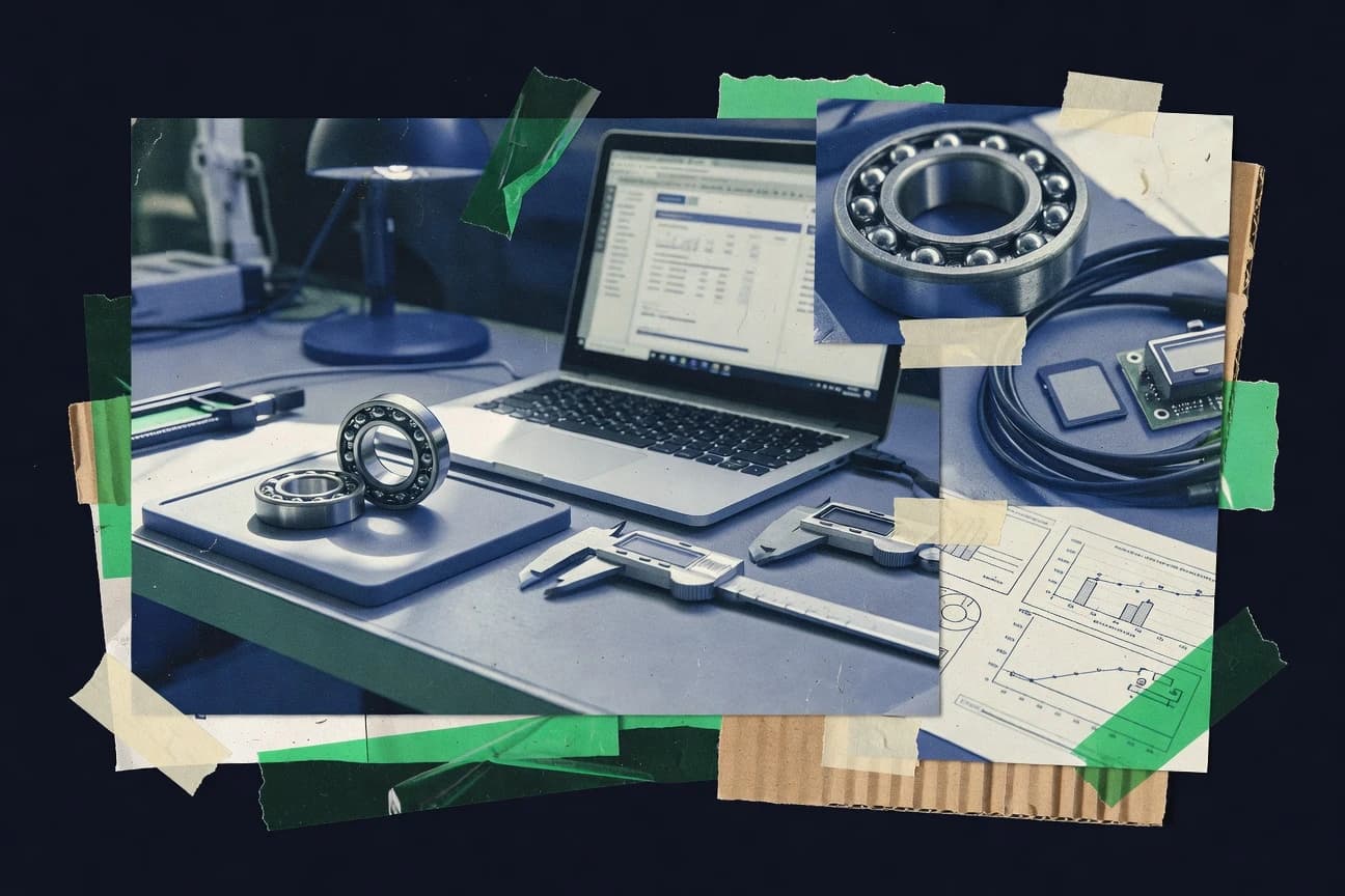
Manufacturing EngineeringTop 10 Best Bearing Software of 2026
Top 10 Bearing Software picks ranked by performance and workflow. Compare SIEMENS NX, ANSYS Mechanical, and ABAQUS to choose faster.

How we ranked these tools
Core product claims cross-referenced against official documentation, changelogs, and independent technical reviews.
Analyzed video reviews and hundreds of written evaluations to capture real-world user experiences with each tool.
AI persona simulations modeled how different user types would experience each tool across common use cases and workflows.
Final rankings reviewed and approved by our editorial team with authority to override AI-generated scores based on domain expertise.
Score: Features 40% · Ease 30% · Value 30%
Gitnux may earn a commission through links on this page — this does not influence rankings. Editorial policy
Editor’s top 3 picks
Three quick recommendations before you dive into the full comparison below — each one leads on a different dimension.
SIEMENS NX
Integrated CAD-to-CAM associativity for geometry-driven machining planning
Built for manufacturers needing high-precision CAD, CAM, and CAE in one workflow.
ANSYS Mechanical
Nonlinear contact with large-deformation capability across static, dynamic, and coupled loading
Built for mechanical simulation teams needing nonlinear contact and multiphysics study depth.
ABAQUS
Nonlinear contact with large deformation in ABAQUS for predicting bearing interface stiffness under load
Built for teams needing high-fidelity bearing mechanics simulation with nonlinear contact and material behavior.
Related reading
Comparison Table
This comparison table evaluates Bearing Software capabilities across common engineering workflows that intersect CAD, CAE, and simulation, including Siemens NX, ANSYS Mechanical, Abaqus, MSC Nastran, and Autodesk Fusion. Readers can use it to compare how each tool supports geometry creation, meshing, solver execution, results handling, and integration paths within a unified Bearing Software environment.
| # | Tool | Category | Overall | Features | Ease of Use | Value |
|---|---|---|---|---|---|---|
| 1 | SIEMENS NX Provides CAD, CAM, and manufacturing engineering workflows to model bearing designs, manage assemblies, and generate toolpaths. | CAD-CAM | 8.3/10 | 9.0/10 | 7.4/10 | 8.2/10 |
| 2 | ANSYS Mechanical Enables finite element analysis to assess bearing stress, contact pressure, deformation, and fatigue-related responses. | FEA simulation | 8.1/10 | 8.7/10 | 7.6/10 | 7.9/10 |
| 3 | ABAQUS Runs advanced nonlinear finite element simulations to model bearing contact behavior and complex material response. | Nonlinear FEA | 8.2/10 | 8.9/10 | 7.4/10 | 7.9/10 |
| 4 | MSC Nastran Performs structural analysis that supports bearing stiffness, vibration, and load-path evaluations. | Structural analysis | 7.8/10 | 8.4/10 | 6.9/10 | 8.0/10 |
| 5 | Autodesk Fusion Combines CAD modeling with CAM toolpath generation for manufacturing-ready bearing parts and prototypes. | CAD-CAM | 8.1/10 | 8.6/10 | 7.6/10 | 7.9/10 |
| 6 | Catia Supports mechanical design and engineering workflows for bearing assemblies and related documentation in an enterprise CAD environment. | Enterprise CAD | 7.9/10 | 8.6/10 | 7.2/10 | 7.8/10 |
| 7 | COMSOL Multiphysics Models coupled physical effects such as fluid-structure interaction and thermal fields relevant to bearing performance. | Multiphysics | 8.0/10 | 8.8/10 | 7.2/10 | 7.6/10 |
| 8 | KeyShot Generates engineering-grade visualizations for bearing design reviews and communication with stakeholders. | Visualization | 8.2/10 | 8.3/10 | 8.6/10 | 7.6/10 |
| 9 | PLM System by Siemens Provides product lifecycle management capabilities that help manage bearing CAD, requirements, and change control across engineering teams. | PLM | 7.5/10 | 8.2/10 | 7.0/10 | 7.1/10 |
| 10 | Tebis Delivers advanced CAM for manufacturing engineering tasks including machining plans for precision bearing parts. | CAM | 7.1/10 | 7.4/10 | 6.9/10 | 7.0/10 |
Provides CAD, CAM, and manufacturing engineering workflows to model bearing designs, manage assemblies, and generate toolpaths.
Enables finite element analysis to assess bearing stress, contact pressure, deformation, and fatigue-related responses.
Runs advanced nonlinear finite element simulations to model bearing contact behavior and complex material response.
Performs structural analysis that supports bearing stiffness, vibration, and load-path evaluations.
Combines CAD modeling with CAM toolpath generation for manufacturing-ready bearing parts and prototypes.
Supports mechanical design and engineering workflows for bearing assemblies and related documentation in an enterprise CAD environment.
Models coupled physical effects such as fluid-structure interaction and thermal fields relevant to bearing performance.
Generates engineering-grade visualizations for bearing design reviews and communication with stakeholders.
Provides product lifecycle management capabilities that help manage bearing CAD, requirements, and change control across engineering teams.
Delivers advanced CAM for manufacturing engineering tasks including machining plans for precision bearing parts.
SIEMENS NX
CAD-CAMProvides CAD, CAM, and manufacturing engineering workflows to model bearing designs, manage assemblies, and generate toolpaths.
Integrated CAD-to-CAM associativity for geometry-driven machining planning
Siemens NX stands out as an integrated CAD CAM CAE suite with deep mold and machining support for complex industrial workflows. The platform combines solid and surface modeling, assembly-aware simulation workflows, and manufacturing process capabilities tied to 3D geometry. It also supports visualization, design for manufacturing checks, and downstream data handoff through robust neutral formats and interoperability options.
Pros
- Tight CAD to CAM associativity reduces rework across manufacturing steps
- Powerful simulation and analysis workflows handle complex assemblies
- Strong surfacing and solids modeling supports high-end geometry creation
- Industrial-grade data management supports large product structures
- Robust interoperability reduces friction in mixed toolchains
Cons
- Advanced workflows require significant training to use efficiently
- Performance can degrade on very large assemblies without tuning
- Setup of workflows like simulation and manufacturing can be time-consuming
Best For
Manufacturers needing high-precision CAD, CAM, and CAE in one workflow
More related reading
ANSYS Mechanical
FEA simulationEnables finite element analysis to assess bearing stress, contact pressure, deformation, and fatigue-related responses.
Nonlinear contact with large-deformation capability across static, dynamic, and coupled loading
ANSYS Mechanical stands out with a mature multiphysics solver stack for stress, deformation, and contact-heavy mechanical simulations. It supports linear static, modal, harmonic, transient dynamics, thermal-stress coupling, and nonlinear contact and large-deformation analysis workflows. Geometry-to-results pipelines integrate CAD cleanup, meshing controls, and detailed postprocessing for stresses, strains, and factor-of-safety style outputs. Solid mechanics capabilities are strong for engineering teams that need repeatable simulation settings and robust nonlinear contact convergence controls.
Pros
- Nonlinear contact and large-deformation analysis with mature convergence controls
- Broad study coverage from static and modal to transient dynamics and harmonic response
- Detailed stress and life-friendly postprocessing with clear result extraction paths
Cons
- Setup complexity can slow turnaround for lightweight or exploratory studies
- Mesh quality management is labor intensive for difficult geometries and contacts
Best For
Mechanical simulation teams needing nonlinear contact and multiphysics study depth
ABAQUS
Nonlinear FEARuns advanced nonlinear finite element simulations to model bearing contact behavior and complex material response.
Nonlinear contact with large deformation in ABAQUS for predicting bearing interface stiffness under load
ABAQUS from 3ds.com stands out with its deep finite element analysis capabilities for mechanical behavior in bearings and adjacent machine components. It supports nonlinear contact, large deformation, and advanced material models that help predict stiffness, stress, and failure-driving responses under realistic loading. Workflow tools like Abaqus/CAE support model building, meshing, and results visualization, while solver options handle coupled thermal, structural, and dynamic scenarios. For bearing software use cases, it shines when physics fidelity matters more than fast, simplified calculations.
Pros
- Nonlinear contact modeling supports realistic bearing loads and interface behavior
- Advanced material and failure analyses capture stress states beyond linear assumptions
- Abaqus/CAE provides structured model building and high-detail results visualization
Cons
- Model setup and solver configuration require significant expertise and validation effort
- Large bearing assemblies can create long solve times for high mesh densities
- Automation for parametric bearing studies is possible but not as streamlined as dedicated tools
Best For
Teams needing high-fidelity bearing mechanics simulation with nonlinear contact and material behavior
More related reading
MSC Nastran
Structural analysisPerforms structural analysis that supports bearing stiffness, vibration, and load-path evaluations.
MSC Nastran solution sequence for modal and transient response analysis
MSC Nastran stands out for its mature, solver-first finite element analysis engine built for complex structural dynamics and vibration work. It supports linear and nonlinear statics, modal analysis, frequency response, transient response, and aeroelastic workflows through integrated MSC solvers and modeling utilities. For Bearing Software users, the core capability is running credible structural and dynamic simulations that can inform bearing housings, mounts, shafts, and supporting components under load and motion. Its strength is deep simulation fidelity, while its limitations often show up as setup and validation overhead for parameterized bearing studies.
Pros
- Broad analysis coverage spanning modal, frequency response, and transient dynamics
- High-fidelity nonlinear capability for challenging bearing-related structural problems
- Strong workflow fit for structural dynamics around shafts, housings, and mounts
Cons
- Model preparation and load definition require experienced FEA setup practices
- Less streamlined for automated bearing-specific parametric studies
- Geometry-to-mesh iteration can be time-consuming for design exploration
Best For
Teams running high-fidelity structural dynamics for bearing supports and housings
Autodesk Fusion
CAD-CAMCombines CAD modeling with CAM toolpath generation for manufacturing-ready bearing parts and prototypes.
Integrated CAD-to-CAM workflow with automatic toolpath generation and post processing
Autodesk Fusion stands out for unifying CAD modeling, CAM manufacturing, and electronics-oriented workflows inside one design environment. It supports parametric solid and surface modeling with assemblies, drawings, and simulation-style validation through manufacturing and design tools. For Bearing Software evaluation, it is strongest when engineering teams need geometry-to-manufacturing continuity with toolpath generation and post-processing. Collaboration and data management depend on Autodesk’s cloud ecosystem and file workflows.
Pros
- Unified CAD to CAM workflow reduces geometry translation overhead
- Strong parametric modeling supports complex parts and design changes
- Toolpath generation with post processing fits common manufacturing setups
- Integrated simulation and verification options improve design validation
Cons
- Steeper learning curve than lightweight CAD for simple tasks
- Assembly management can become slower on large models
- Collaboration relies heavily on Autodesk cloud file conventions
- Some advanced workflows require careful setup and validation
Best For
Engineering teams creating parametric parts and turning them into CAM toolpaths
Catia
Enterprise CADSupports mechanical design and engineering workflows for bearing assemblies and related documentation in an enterprise CAD environment.
Parametric Generative Shape Design and associative design history for complex bearing surfaces
CATIA by 3ds.com stands out for deep, CAD-first product engineering capabilities and strong digital thread positioning across design and manufacturing. It supports advanced mechanical design, surface modeling, and parametric assemblies alongside simulation-oriented workflows through connected environments. For bearings and other engineered components, it enables toleranced 3D modeling, kinematic and analysis workflows, and production documentation outputs from a consistent master model. The primary limitation is that effective use depends on disciplined data management and specialized training for complex assemblies and variation handling.
Pros
- Powerful parametric and surface modeling for accurate bearing geometry
- Strong assembly and product structure management for complex bearing designs
- Robust downstream documentation from the same controlled 3D source
Cons
- Steep learning curve for advanced workflows and feature modeling
- Complex setups increase reliance on strong governance of model variants
- Integration across specialized apps can add workflow overhead for teams
Best For
Engineering teams building bearing models needing high-accuracy CAD and documentation
More related reading
COMSOL Multiphysics
MultiphysicsModels coupled physical effects such as fluid-structure interaction and thermal fields relevant to bearing performance.
Multiphysics coupling using the COMSOL interface and automatic field-to-field integration
COMSOL Multiphysics stands out for coupling many physics domains inside a single simulation workflow with a shared geometry and mesh. It supports finite element analysis for structural mechanics, fluid flow, heat transfer, electromagnetics, and multiphysics interactions such as thermal-stress coupling. Built-in CAD import, parametric studies, and solver orchestration help move from model setup to results like fields, derived quantities, and sensor-like postprocessing outputs. The approach is powerful for analysis-driven engineering, but it requires strong modeling discipline and validation to avoid misleading results.
Pros
- Strong multiphysics coupling with shared meshing and consistent field transfer
- Comprehensive finite element feature set for complex geometries and boundary conditions
- Parametric sweeps and studies streamline design exploration and scenario comparison
- Rich postprocessing supports derived metrics, plots, and probe-style evaluations
Cons
- Geometry preparation and meshing often require expert control to avoid solver issues
- Model setup depth can slow iteration for exploratory workflows and quick prototypes
- Advanced multiphysics models can demand heavy compute resources
Best For
Engineering teams running validated multiphysics simulations for design and analysis
KeyShot
VisualizationGenerates engineering-grade visualizations for bearing design reviews and communication with stakeholders.
Real-time rendering with immediate physically based material and lighting updates
KeyShot stands out with its real-time, photoreal rendering workflow and immediate visual feedback. It supports CAD model import, physically based materials, studio lighting setups, and animation for product visualization. The tool also enables project-level organization for scenes, render outputs, and camera moves that supports repeatable presentation assets. For bearing-focused work, it is strong for visualizing assemblies, finishes, and mechanical details without deep rendering customization.
Pros
- Real-time preview makes materials and lighting changes instant
- Physically based rendering delivers consistent photoreal product imagery
- CAD import and scene organization support repeatable bearing assembly visuals
- Animation and camera tooling helps create review-ready product sequences
Cons
- Advanced rendering controls can require time to fully master
- Large assemblies can slow interaction during look development
- Precision engineering callouts are limited compared with CAD-centric tools
Best For
Teams needing fast photoreal bearing and assembly visualizations for reviews
More related reading
PLM System by Siemens
PLMProvides product lifecycle management capabilities that help manage bearing CAD, requirements, and change control across engineering teams.
Engineering change management with controlled release tied to product structure baselines
Siemens PLM System stands out for tying digital product data to engineering workflows across CAD, engineering change management, and manufacturing handoff. It supports structured product data management with version control, configurable baselines, and traceability across product lifecycle processes. Integration with Siemens engineering tools enables consistent requirements capture, review cycles, and controlled release of design and related artifacts.
Pros
- Strong engineering change and revision control tied to product structures
- Broad integration path across Siemens design and manufacturing workflows
- Detailed traceability from requirements to released product data artifacts
Cons
- Modeling and governance setup can require significant configuration discipline
- User experience can feel heavy for teams focused on simple document control
- Workflow customization often demands specialist knowledge of PLM configuration
Best For
Manufacturing and engineering teams needing controlled product data with deep workflow governance
Tebis
CAMDelivers advanced CAM for manufacturing engineering tasks including machining plans for precision bearing parts.
Integrated process planning and CAM execution with toolpath simulation in one manufacturing workflow
Tebis stands out with a model-to-machining workflow that connects design intent to process planning for bearings and related rotating parts. Its core capabilities include CAM programming for turning, milling, and gear manufacturing, plus simulation to validate toolpaths and reduce collision and process risk. The platform also supports NC data management and shop-floor oriented execution through integrated data handling for production use.
Pros
- End-to-end workflow from CAD data to executable NC programs for machining processes
- Toolpath simulation helps validate setups and reduce machining rework risk
- Strong support for multi-axis programming patterns common in bearing-related geometries
Cons
- Setup and process knowledge can be heavy for teams without established machining standards
- Specialized bearing workflows may require deeper configuration than general CAM packages
- Usability depends on consistent data quality and disciplined naming conventions
Best For
Manufacturers needing high-accuracy CAM programming for bearing production and process validation
How to Choose the Right Bearing Software
This buyer’s guide covers Bearing Software options including SIEMENS NX, ANSYS Mechanical, ABAQUS, MSC Nastran, Autodesk Fusion, CATIA, COMSOL Multiphysics, KeyShot, PLM System by Siemens, and Tebis. It translates the tools’ modeled workflows like nonlinear contact simulation, CAD-to-CAM associativity, and NC-ready process planning into decision criteria. It also highlights the exact setup friction points like nonlinear solver convergence, mesh management, and large-assembly performance across these products.
What Is Bearing Software?
Bearing Software covers engineering tools used to design bearing geometry, validate performance, and prepare manufacturing execution for bearing parts and assemblies. It solves problems like geometry-to-analysis handoff, predicting bearing stress and deformation, and generating machining toolpaths with collision risk controls. It also includes product data control for change management using systems like PLM System by Siemens. Example categories include simulation suites like ANSYS Mechanical for nonlinear contact behavior and manufacturing-centric tools like Tebis for CAD data to NC program generation.
Key Features to Look For
The right feature set depends on whether the bearing workflow prioritizes geometry-driven manufacturing, validated mechanical behavior, or controlled engineering change across a digital product structure.
Geometry-driven CAD-to-CAM associativity
SIEMENS NX supports integrated CAD-to-CAM associativity so machining planning stays linked to the modeled geometry and reduces rework when design changes occur. Autodesk Fusion also targets geometry-to-manufacturing continuity with automatic toolpath generation and post processing.
Nonlinear contact and large-deformation mechanics
ANSYS Mechanical provides nonlinear contact with large-deformation capability across static, dynamic, and coupled loading so bearing interface behavior can be evaluated under realistic constraints. ABAQUS delivers nonlinear contact with large deformation to predict bearing interface stiffness under load when physical fidelity matters most.
Structural dynamics for bearing supports and housings
MSC Nastran supports modal, frequency response, and transient response analysis so bearing housings, mounts, and shafts can be evaluated under vibration and load-path conditions. This fits engineering teams that need high-fidelity structural dynamics rather than only static stress checks.
Multiphysics coupling on shared geometry and mesh
COMSOL Multiphysics couples multiple physics domains using a shared geometry and mesh so thermal-stress coupling and other field interactions can be simulated within one orchestrated workflow. This approach is useful for design cases where bearing performance depends on more than solid mechanics.
Parametric, associative CAD for complex bearing surfaces
CATIA emphasizes parametric generative shape design and associative design history so complex bearing surfaces remain traceable to design intent. SIEMENS NX also provides strong solids and surfacing modeling for high-end geometry creation in complex industrial workflows.
Manufacturing process planning with NC program execution support
Tebis connects design intent to machining plans and supports simulation to validate toolpaths and reduce collision and process risk. It also manages NC data for shop-floor oriented execution with toolpath simulation aimed at bearing production.
How to Choose the Right Bearing Software
Selection should start from the bearing workflow stage that creates the most risk, then match tools with the exact capabilities needed at that stage.
Pick the primary goal: manufacturing readiness or mechanical fidelity
For geometry-driven machining planning, SIEMENS NX excels with integrated CAD-to-CAM associativity and geometry-driven toolpath setup. For predicting bearing interface stiffness and stress under realistic loading, ANSYS Mechanical and ABAQUS excel because both provide nonlinear contact with large-deformation capability, with ANSYS Mechanical spanning static, modal, harmonic, transient dynamics, and coupled thermal-stress workflows.
Match the required physics depth to the simulation tool
If nonlinear contact convergence and large-deformation behavior across coupled study types are required, ANSYS Mechanical is a fit because it supports nonlinear contact with mature convergence controls. If the workflow requires advanced material models and failure-driving response under realistic bearing loads, ABAQUS offers deep nonlinear material and failure analysis with structured model building in Abaqus/CAE.
Choose structural dynamics tools for vibration and load-path cases
For bearing housings, mounts, and shafts where vibration behavior matters, MSC Nastran fits because it provides modal, frequency response, and transient response analysis sequences. This selection aligns with teams that need credible structural and dynamic simulations and can manage load definition and experienced FEA setup practices.
Select multiphysics when thermal or fluid effects influence bearing performance
When bearing performance depends on coupled effects like thermal-stress interactions, COMSOL Multiphysics supports multiphysics coupling using shared meshing and field-to-field integration. This selection suits validated multiphysics workflows where parameter sweeps and probe-style postprocessing are part of the engineering process.
Use CAD, PLM, and visualization tools to reduce rework and communication gaps
For teams needing high-accuracy bearing CAD plus documentation tied to a controlled master model, CATIA supports parametric generative shape design and associative design history. For engineering change management across product structures, PLM System by Siemens ties version control, baselines, and traceability to product lifecycle processes. For stakeholder-ready bearing assembly visuals, KeyShot provides real-time photoreal rendering with physically based materials and repeatable camera sequences.
Who Needs Bearing Software?
Bearing software buying decisions map to distinct engineering roles, simulation scopes, and manufacturing execution responsibilities reflected in each tool’s best-fit audience.
Manufacturers needing CAD, CAM, and CAE in one geometry-linked workflow
SIEMENS NX fits manufacturers needing high-precision CAD, CAM, and CAE because it delivers integrated CAD-to-CAM associativity and supports powerful simulation and analysis workflows tied to 3D geometry.
Mechanical simulation teams focused on nonlinear contact and multiphysics study coverage
ANSYS Mechanical fits mechanical simulation teams that need nonlinear contact with large-deformation capability across static and dynamic studies including thermal-stress coupling. COMSOL Multiphysics fits teams requiring validated multiphysics simulations with shared geometry and mesh orchestration for coupled field effects.
Teams requiring high-fidelity bearing mechanics with advanced nonlinear material response
ABAQUS fits teams that prioritize physics fidelity over speed because it supports nonlinear contact, large deformation, and advanced material and failure analyses. This audience also needs Abaqus/CAE structured model building and detailed postprocessing workflows.
Manufacturing teams running machining plans, NC execution, and toolpath risk validation
Tebis fits manufacturers needing high-accuracy CAM programming for bearing production because it delivers end-to-end CAD data to executable NC programs with toolpath simulation for collision and process risk reduction. For general CAD-to-toolpath workflows that combine design and manufacturing inside one environment, Autodesk Fusion supports integrated CAD-to-CAM workflow with automatic toolpath generation and post processing.
Common Mistakes to Avoid
Common pitfalls cluster around choosing the wrong workflow depth for the engineering risk, underestimating setup burden, and neglecting model governance for change control.
Over-scoping nonlinear contact simulation without planning for setup effort
Nonlinear contact and large-deformation work adds model and mesh complexity in ANSYS Mechanical and ABAQUS, which slows turnaround when exploratory studies are the priority. Avoid assuming fast iterations in MSC Nastran as geometry-to-mesh iteration and load definition preparation can take time for design exploration.
Choosing a CAD-first tool without a downstream path to machining execution
CATIA and SIEMENS NX can both excel at high-accuracy bearing geometry and associative history, but CAD-centric planning still needs a concrete CAM execution workflow. SIEMENS NX reduces this gap via integrated CAD-to-CAM associativity, while Autodesk Fusion and Tebis focus directly on toolpath generation and NC-ready execution.
Neglecting meshing and mesh quality management in coupled or contact-heavy models
ANSYS Mechanical and COMSOL Multiphysics both require strong modeling discipline because geometry preparation and meshing control directly affect solver behavior. ABAQUS also incurs long solve times for large bearing assemblies with high mesh densities, which magnifies the cost of poor mesh strategy.
Skipping product structure governance and release traceability for multi-team bearing development
PLM System by Siemens provides engineering change management with controlled release tied to product structure baselines, and skipping this can create revision confusion when multiple teams reuse bearing CAD and requirements. This is especially relevant when CATIA or SIEMENS NX design variants must remain governed through controlled baselines and traceability chains.
How We Selected and Ranked These Tools
We evaluated each tool on three sub-dimensions with features weighted at 0.4, ease of use weighted at 0.3, and value weighted at 0.3. The overall rating is computed as overall = 0.40 × features + 0.30 × ease of use + 0.30 × value. SIEMENS NX separated itself from lower-ranked tools through feature performance tied to integrated CAD-to-CAM associativity for geometry-driven machining planning, which directly reduces rework across manufacturing steps. Ease of use and value were then applied on top of that feature strength to produce the final ranking.
Frequently Asked Questions About Bearing Software
Which tool handles bearing-focused CAD-to-machining planning with the least handoff between design and CAM?
Siemens NX is built for geometry-driven manufacturing because its CAD-to-CAM associativity keeps toolpaths linked to 3D design intent. Tebis also targets bearing production with a model-to-machining workflow that pairs CAM programming for turning and milling with toolpath simulation for process risk reduction.
Which software is best for predicting bearing interface stiffness using nonlinear contact and large deformation?
ABAQUS is the most direct fit because it supports nonlinear contact and large deformation with advanced material behavior used to model bearing interfaces under realistic load. ANSYS Mechanical is also strong for contact-heavy multiphysics problems, especially when nonlinear convergence controls are required for repeatable study setups.
What option is most suitable for vibration and transient response on bearing housings and mounts?
MSC Nastran is solver-first for structural dynamics, supporting modal analysis, frequency response, and transient response to evaluate housing and supporting components. ANSYS Mechanical can cover transient dynamics too, but MSC Nastran is often favored when structural dynamics workflows and solution sequences drive the engineering process.
Which tool supports multiphysics bearing analysis by sharing geometry and mesh across physics domains?
COMSOL Multiphysics is designed around a shared geometry and mesh, enabling coupled structural mechanics with heat transfer and thermal-stress interaction. For bearing work, this makes it practical to analyze how temperature fields and structural response affect each other without rebuilding separate models in different tools.
Which package is strongest when the workflow must stay connected to a controlled engineering change and traceability process?
Siemens PLM System focuses on structured product data management, including version control, configurable baselines, and traceability across lifecycle workflows. It complements engineering tools by tying released design and related artifacts to a controlled product structure backbone.
Which option is better for parameterized design of bearing components with disciplined documentation outputs?
CATIA supports CAD-first product engineering with parametric assemblies and detailed documentation built from a consistent master model. Catia also helps for bearing surfaces where associative design history supports kinematics and analysis-ready geometry, while Siemens NX emphasizes integrated CAD and downstream manufacturing workflows.
Which tool is most appropriate when bearing teams need geometry-to-results workflows with detailed contact and multiphysics postprocessing?
ANSYS Mechanical offers a geometry-to-results pipeline that integrates CAD cleanup, meshing controls, and postprocessing for stresses and deformation fields. It is particularly effective for contact-heavy nonlinear studies across static, dynamic, and coupled loading conditions.
Which software should be used for fast photoreal bearing and assembly visualization during technical reviews?
KeyShot is optimized for real-time photoreal rendering with immediate feedback, which is useful for presenting bearing assemblies, finishes, and mechanical details. Its workflow supports reusable project-level scene organization and camera moves, reducing iteration time during review cycles.
What common problem appears when using high-fidelity bearing simulation tools, and how do teams address it?
High-fidelity FEA tools such as ABAQUS and MSC Nastran can fail to converge or produce misleading results when nonlinear contact setup, validation, or boundary conditions are inconsistent. COMSOL Multiphysics adds another risk because multiphysics coupling demands modeling discipline, but its shared geometry and mesh can reduce mismatch errors across coupled domains.
Conclusion
After evaluating 10 manufacturing engineering, SIEMENS NX stands out as our overall top pick — it scored highest across our combined criteria of features, ease of use, and value, which is why it sits at #1 in the rankings above.
Use the comparison table and detailed reviews above to validate the fit against your own requirements before committing to a tool.
Tools reviewed
Referenced in the comparison table and product reviews above.
Keep exploring
Comparing two specific tools?
Software Alternatives
See head-to-head software comparisons with feature breakdowns, pricing, and our recommendation for each use case.
Explore software alternatives→In this category
Manufacturing Engineering alternatives
See side-by-side comparisons of manufacturing engineering tools and pick the right one for your stack.
Compare manufacturing engineering tools→FOR SOFTWARE VENDORS
Not on this list? Let’s fix that.
Our best-of pages are how many teams discover and compare tools in this space. If you think your product belongs in this lineup, we’d like to hear from you—we’ll walk you through fit and what an editorial entry looks like.
Apply for a ListingWHAT THIS INCLUDES
Where buyers compare
Readers come to these pages to shortlist software—your product shows up in that moment, not in a random sidebar.
Editorial write-up
We describe your product in our own words and check the facts before anything goes live.
On-page brand presence
You appear in the roundup the same way as other tools we cover: name, positioning, and a clear next step for readers who want to learn more.
Kept up to date
We refresh lists on a regular rhythm so the category page stays useful as products and pricing change.