GITNUXSOFTWARE ADVICE
Manufacturing EngineeringTop 8 Best Electronics Schematic Software of 2026
Top 10 Electronics Schematic Software picks ranked and compared for 2026. Evaluate KiCad, Altium Designer, and EAGLE to choose fast.

How we ranked these tools
Core product claims cross-referenced against official documentation, changelogs, and independent technical reviews.
Analyzed video reviews and hundreds of written evaluations to capture real-world user experiences with each tool.
AI persona simulations modeled how different user types would experience each tool across common use cases and workflows.
Final rankings reviewed and approved by our editorial team with authority to override AI-generated scores based on domain expertise.
Score: Features 40% · Ease 30% · Value 30%
Gitnux may earn a commission through links on this page — this does not influence rankings. Editorial policy
Editor’s top 3 picks
Three quick recommendations before you dive into the full comparison below — each one leads on a different dimension.
KiCad
Rules-driven ERC with schematic annotation that keeps nets and footprints aligned
Built for teams building mixed-size PCB designs needing reliable schematic-to-layout consistency.
Altium Designer
Editor pickIntegrated schematic-to-layout synchronization with constraint-based electrical rule checking
Built for teams building PCB-heavy products needing strict rules and reliable connectivity sync.
Autodesk EAGLE
Editor pickCross-probing with instant net connectivity validation between schematic and PCB
Built for designers needing reliable schematic capture and PCB layout in one editor suite.
Related reading
Comparison Table
This comparison table evaluates electronics schematic software by key engineering factors such as schematic capture workflow, library management, design rule support, and file compatibility across common EDA toolchains. It also contrasts pricing model, collaboration features, and simulation or PCB handoff capabilities for tools including KiCad, Altium Designer, Autodesk EAGLE, EasyEDA, Zuken CR-8000, and additional alternatives.
KiCad
open-source CADOpen-source electronics CAD for schematic capture and PCB layout with advanced libraries, ERC checks, and export support.
Rules-driven ERC with schematic annotation that keeps nets and footprints aligned
KiCad stands out for fully integrated open-source ECAD that covers schematic capture and PCB layout in one project flow. It supports hierarchical schematics, reusable symbols, and footprint linking to drive consistent schematic-to-board implementation.
The tool includes ERC rule checking, netlist export, and annotation workflows that reduce schematic-to-layout mismatches. Its library system supports local symbol and footprint management, enabling repeatable designs across multiple projects.
- +Hierarchical schematics support complex designs with clear sheet organization
- +ERC and DRC help catch electrical and layout issues early
- +Robust schematic-to-PCB net connectivity with footprint assignment
- +Local symbol and footprint libraries support controlled, repeatable projects
- +Keyboard-driven editing speeds up wire, component, and label placement
- –Learning curve is steep for schematic and footprint conventions
- –Library management can be time-consuming for large symbol sets
- –Complex projects may feel slower than commercial alternatives
- –Advanced automation needs scripting knowledge beyond basic workflows
Best for: Teams building mixed-size PCB designs needing reliable schematic-to-layout consistency
Altium Designer
pro desktop CADProfessional electronics design software that combines schematic capture, PCB layout, and constraint-driven rules for manufacturing-ready outputs.
Integrated schematic-to-layout synchronization with constraint-based electrical rule checking
Altium Designer stands out with a unified schematic and PCB design workflow built around a single component and netlist source of truth. The schematic editor supports hierarchical designs, rich electrical rules checks, and cross-probing to PCB layout objects.
It offers advanced library management with symbol and footprint association, plus simulation-focused project structures. Design integrity is strengthened through constraint-driven updates and automated synchronization between schematic connectivity and layout.
- +Tight schematic-to-PCB connectivity with fast cross-probing
- +Strong hierarchical schematic tools with reusable sheets
- +Robust electrical rules checking with constraint-driven workflow
- +Advanced component library linking for symbols and footprints
- +Project-level organization supports large multi-sheet designs
- –Complex UI can slow down schematic creation for newcomers
- –Hierarchy and rules setups can feel heavy for small boards
- –Simulation flows require careful configuration and model management
- –Large library and project databases can increase maintenance overhead
Best for: Teams building PCB-heavy products needing strict rules and reliable connectivity sync
Autodesk EAGLE
desktop CADDesktop electronics CAD that supports schematic capture, PCB layout, and CAM file generation for fabrication workflows.
Cross-probing with instant net connectivity validation between schematic and PCB
Autodesk EAGLE stands out for its tight workflow between schematic capture and PCB layout inside one editor suite. It supports hierarchical schematics, net connectivity checking, and design rule enforcement during PCB creation.
The libraries ecosystem includes device packs and symbol and footprint management that fits production-ready component reuse. Board variants and export tools help teams maintain consistent designs across revisions.
- +Unified schematic-to-PCB workflow reduces connectivity errors
- +ERC and net connectivity checks catch issues before layout export
- +Hierarchical schematics support large designs with reusable blocks
- +Strong symbol and footprint management for consistent part libraries
- –Less suited for large multi-board system modeling than enterprise suites
- –Scripting customization relies on EAGLE-specific workflows and tooling
- –Advanced simulation and verification depth is limited versus dedicated tools
- –Library maintenance can become tedious without strict governance
Best for: Designers needing reliable schematic capture and PCB layout in one editor suite
EasyEDA
cloud EDACloud and desktop-capable schematic and PCB editor that provides real-time collaboration and fabrication-ready exports.
Schematic-to-PCB linking that preserves nets during layout and updates
EasyEDA stands out for turning a web browser into a full schematic and PCB drafting workspace. It supports standard capture workflows with schematic symbols, footprints, and net connectivity across projects.
The component library includes verified parts and footprints that can be reused between schematics and PCB layouts. Export and fabrication prep are built into the workflow with tools for generating production-ready PCB outputs.
- +Browser-based schematic capture with real-time design synchronization
- +Tightly linked schematic-to-PCB net connectivity reduces layout mismatches
- +Large searchable component library with reusable footprints
- +Gerber and drill export supports common manufacturing workflows
- +Integrated simulation support for common electronics validation tasks
- –Complex multi-sheet designs can feel harder to navigate
- –Library footprint quality varies across third-party contributed parts
- –Advanced constraint and routing control can be less granular than pro CAD
- –Large projects may become slower in the browser editor
Best for: Teams needing quick web-based schematic capture and PCB generation
Zuken CR-8000
schematic documentationSchematic design platform used for complex engineering documentation with structured data handling and downstream publishing.
Variant and hierarchical schematic data management with change-aware propagation
Zuken CR-8000 stands out with a scalable schematic and cable harness design flow aimed at industrial electronics programs. It supports hierarchical schematics, structured data management, and variant control for large product families.
The tool is built for engineering change workflows, routing interfaces, and bill of materials linkage across releases. Tight integration with Zuken layout and PCB design enables consistent component and net data from schematic through downstream documentation.
- +Hierarchical schematic management for complex, multi-subsystem designs
- +Variant control supports product family reuse with controlled changes
- +Engineering change propagation keeps nets and component references aligned
- +Strong data model links schematic capture to downstream BOM and documentation
- +Integration paths to layout and PCB design reduce re-entry of design intent
- –Constrained workflows for teams wanting lightweight, quick-only schematic capture
- –Cable harness and interconnect tasks can add setup overhead for small projects
- –Best results rely on consistent data discipline and project configuration
- –User interface complexity can slow adoption for schematic-only users
Best for: Industrial engineering teams managing hierarchical schematics and variant-based programs
SPICE-based schematic with Qucs
schematic plus simulationSchematic entry with integrated circuit simulation for validating electronics designs before fabrication and manufacturing transfer.
Schematic-driven SPICE netlisting with in-app parameter sweeps and plots
Qucs provides SPICE-based circuit simulation coupled with a schematic editor and component library tailored for electronics design. Schematic capture supports assigning SPICE netlists to graphical parts so the same drawing can drive simulation runs.
Analysis workflows include DC, AC, transient, and parameter sweeps, with results plotted inside the application for quick iteration. The tool focuses on file-based projects that keep schematics, simulation setups, and plotted outputs together for repeatable experiments.
- +SPICE-driven simulation is tightly integrated with schematic capture
- +Multi-domain analyses include DC, AC, and transient within one workflow
- +Parameter sweeps enable automated exploration of design variations
- +Built-in plotting shows simulation waveforms and responses directly
- –Complex mixed-signal designs can require manual workaround effort
- –Large libraries and deep hierarchies can make navigation slower
- –Error reporting can be harder to trace to specific schematic elements
Best for: Designers needing SPICE simulation linked to schematic capture
Proteus
virtual prototypingElectronics design and simulation environment that supports schematic capture and virtual prototyping for manufacturing validation.
Virtual instruments with schematic-linked probes for mixed-signal stimulus and measurement
Proteus stands out for its tight integration between schematic capture and circuit simulation using a single workspace. It supports mixed-signal design with SPICE-based simulation and virtual instrumentation to observe signals without separate test hardware.
The symbol and footprint libraries help translate captured circuits into physical-ready layouts when the workflow includes PCB design tools. It also provides debugging-style workflows through probes, stimulus sources, and simulation waveform viewing tied to the schematic.
- +Schematic-to-simulation workflow keeps test setup aligned with the design
- +Virtual instruments visualize signals using oscilloscope, logic, and function tools
- +SPICE-based analysis supports analog and mixed-signal verification
- –Large mixed-signal projects can become slow to simulate interactively
- –Deep model accuracy depends on available component SPICE definitions
- –Complex netlists require careful hierarchy and naming to trace signals
Best for: Electronics teams validating analog and mixed-signal circuits before hardware builds
Nordic Semiconductor nRF Connect for Desktop
hardware workflowDesign and verification toolchain for Nordic electronics workflows that supports firmware integration checks alongside hardware planning.
Device discovery and control via the nRF Connect for Desktop toolchain
Nordic Semiconductor nRF Connect for Desktop stands out as a hardware-centric toolset that connects directly to Nordic devices from a desktop workflow. It provides firmware and device interaction through nRF command-line tooling and device services rather than authoring traditional electronics schematics.
Core capabilities focus on discovery, programming support, logging integration, and debugging workflows across supported Nordic boards and modules. For schematic capture tasks, it serves more as a companion to the nRF development stack than as a full schematic editor.
- +Direct connection workflows for Nordic boards and modules
- +Centralized device discovery for faster debug iteration
- +Integrates with logging and programming steps
- –Not a dedicated electronics schematic capture editor
- –Schematic-specific features like netlists and footprints are absent
- –Best value depends on Nordic device toolchain support
Best for: Teams needing fast Nordic device programming and debug orchestration
How to Choose the Right Electronics Schematic Software
This buyer’s guide covers how to evaluate electronics schematic software using concrete capabilities from KiCad, Altium Designer, Autodesk EAGLE, EasyEDA, Zuken CR-8000, Qucs, Proteus, and Nordic Semiconductor nRF Connect for Desktop. It also explains when SPICE-linked schematic simulation and virtual-instrument debugging matter, using Qucs and Proteus as the primary examples. The guide concludes with a selection framework, common pitfalls, and a tool-specific FAQ spanning all ten tools.
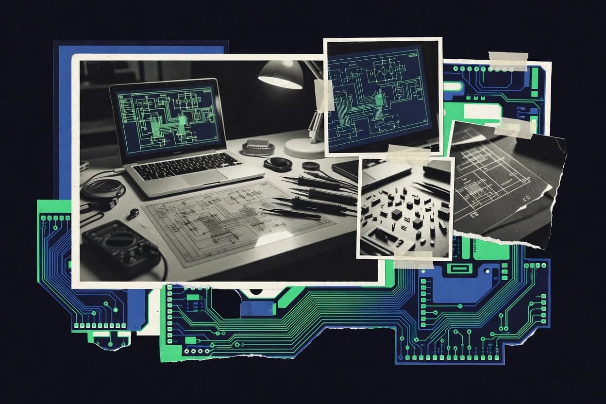
What Is Electronics Schematic Software?
Electronics schematic software creates and manages circuit diagrams that capture parts, nets, and connectivity so designs can be verified and turned into hardware outputs. It solves connectivity consistency problems by running checks like ERC and net connectivity validation during schematic capture and by synchronizing schematic-to-layout states in tools such as KiCad, Altium Designer, Autodesk EAGLE, and EasyEDA. It is used by PCB designers, industrial engineering teams, and electronics validation teams who need either fabrication-ready design flows or simulation-driven verification. It also appears in specialized workflows where a schematic directly drives SPICE simulation in Qucs and where schematic-linked probes support measurement-style debugging in Proteus.
Key Features to Look For
The right feature set determines whether schematic intent stays correct during hierarchy expansion, layout handoff, and simulation or verification.
Rules-driven ERC and net integrity checks
KiCad provides rules-driven ERC with schematic annotation that keeps nets and footprints aligned, which directly reduces schematic-to-PCB mismatches. Altium Designer strengthens design integrity through robust electrical rules checking with constraint-driven synchronization between schematic connectivity and PCB objects.
Schematic-to-PCB connectivity synchronization and cross-probing
Altium Designer offers integrated schematic-to-layout synchronization with fast cross-probing that ties schematic connectivity to PCB layout objects. Autodesk EAGLE also supports cross-probing with instant net connectivity validation between schematic and PCB, which speeds up correction loops during board creation.
Hierarchical schematic management and reusable sheet structures
KiCad supports hierarchical schematics with clear sheet organization, which helps teams manage complex designs without losing context. Zuken CR-8000 and Autodesk EAGLE also emphasize hierarchical schematic support, where reusable blocks and structured navigation matter for large multi-sheet programs.
Linked symbol and footprint or part library governance
KiCad uses footprint linking and local symbol and footprint libraries so symbol-to-footprint implementation stays consistent across projects. Altium Designer pairs advanced component library management with symbol and footprint association, while Autodesk EAGLE focuses on symbol and footprint management for production-ready component reuse.
Simulation and schematic-driven SPICE netlisting
Qucs couples a schematic editor with SPICE-based simulation by assigning SPICE netlists to graphical parts, so the same schematic drives DC, AC, transient, and parameter sweeps. Proteus supports SPICE-based analysis in a schematic-to-simulation workflow and adds virtual instruments that make analog and mixed-signal observation practical during verification.
Variant control and change-aware propagation for engineering programs
Zuken CR-8000 provides variant and hierarchical schematic data management with change-aware propagation, which keeps nets and component references aligned across releases. This structured change propagation is a key differentiator for industrial electronics programs managing product family reuse.
How to Choose the Right Electronics Schematic Software
Selecting the right tool depends on whether the workflow centers on fabrication-ready PCB connectivity, program-scale change control, or schematic-linked simulation and measurement.
Map the workflow to schematic-to-layout connectivity needs
If the primary requirement is reliable schematic-to-PCB net connectivity, KiCad excels with rules-driven ERC and robust schematic-to-PCB connectivity with footprint assignment. Altium Designer and Autodesk EAGLE also prioritize connectivity integrity through integrated synchronization or cross-probing, so schematic intent can be validated against PCB objects during layout.
Decide how hierarchy and change management must work
For multi-sheet designs where hierarchical schematics and reusable organization are core, KiCad and Autodesk EAGLE support hierarchical design structures that reduce schematic management friction. For industrial engineering programs that require variant control and engineering change propagation, Zuken CR-8000 provides variant and hierarchical schematic data management with change-aware propagation and BOM-linked downstream documentation.
Choose library management based on symbol-to-footprint consistency
For teams that need controlled, repeatable projects, KiCad supports local symbol and footprint libraries and uses footprint linking to keep schematic-to-board implementation aligned. Altium Designer adds advanced component library linking and constraint-driven synchronization, while Autodesk EAGLE emphasizes consistent symbol and footprint management for reusable part libraries.
Include simulation in the selection only if the schematic must drive verification
If schematic capture must directly drive SPICE analysis with parameter sweeps and plots, Qucs provides schematic-driven SPICE netlisting and in-app plotting for DC, AC, transient, and parameter sweep results. If mixed-signal validation needs virtual measurement behavior tied to the schematic, Proteus provides virtual instruments with schematic-linked probes and SPICE-based analog and mixed-signal verification.
Pick the tool that matches the collaboration and platform constraints
For quick browser-based schematic capture and PCB generation workflows, EasyEDA runs schematic and PCB drafting in a web browser and emphasizes schematic-to-PCB linking that preserves nets during layout and updates. For Nordic-focused firmware and hardware integration workflows that do not author traditional schematics, Nordic Semiconductor nRF Connect for Desktop functions as a companion that supports device discovery and control through the nRF Connect toolchain rather than providing netlists and footprints.
Who Needs Electronics Schematic Software?
Electronics schematic software serves distinct roles ranging from PCB connectivity integrity to program-scale change control and schematic-linked simulation or Nordic device orchestration.
Teams building mixed-size PCB designs that depend on consistent schematic-to-layout behavior
KiCad is a strong fit because it supports hierarchical schematics and delivers rules-driven ERC with schematic annotation plus robust schematic-to-PCB net connectivity with footprint assignment. Autodesk EAGLE also targets this workflow with unified schematic-to-PCB design and cross-probing for instant net connectivity validation.
Product teams building PCB-heavy systems that need strict electrical rule checking and synchronization
Altium Designer fits PCB-heavy product development because it offers integrated schematic-to-layout synchronization with constraint-driven electrical rule checking and fast cross-probing. The single source-of-truth workflow between schematic and PCB objects reduces connectivity drift during iterative board changes.
Industrial electronics groups that manage product families, variants, and engineering change propagation
Zuken CR-8000 is built for hierarchical schematic management and structured data handling that keeps nets and component references aligned across variants and releases. It also links schematic capture to downstream BOM and documentation through engineering change workflows.
Designers validating analog or mixed-signal circuits with measurement-style debugging
Proteus is designed for mixed-signal verification with virtual instruments and schematic-linked probes that support oscilloscope, logic, and function-style observation. Qucs targets SPICE simulation linked to schematic capture with DC, AC, transient, parameter sweeps, and in-app plotting.
Common Mistakes to Avoid
Recurring pitfalls in electronics schematic workflows come from mismatched connectivity checks, inadequate library governance, and selecting a tool that does not cover the required engineering task.
Ignoring schematic-to-PCB connectivity validation
Teams that skip strong ERC or cross-probing frequently lose track of which nets map to which PCB objects during layout iteration, and this is exactly what KiCad, Altium Designer, and Autodesk EAGLE are built to prevent. KiCad applies rules-driven ERC with schematic annotation, Altium Designer synchronizes schematic connectivity to PCB layout via constraint-driven workflows, and Autodesk EAGLE provides instant net connectivity validation through cross-probing.
Underestimating hierarchy and navigation friction in large projects
Complex multi-sheet designs can feel slower or harder to navigate when hierarchy workflows are not a match for team usage, which is why KiCad and Autodesk EAGLE focus on hierarchical schematic organization. EasyEDA also supports multi-sheet capture but can feel harder to navigate for complex multi-sheet designs, and large browser projects may become slower in the editor.
Letting library quality degrade across symbol or footprint sets
Library drift can cause schematic-to-board mismatches, and KiCad mitigates this by supporting local symbol and footprint libraries plus footprint linking. EasyEDA can suffer from footprint quality variation across third-party contributed parts, and large libraries in Altium Designer can increase maintenance overhead if governance is weak.
Choosing a Nordic device orchestration tool for traditional schematic capture
Nordic Semiconductor nRF Connect for Desktop is not a dedicated schematic capture editor because it focuses on device discovery, programming support, logging integration, and debugging orchestration through the nRF Connect toolchain. Teams needing nets and footprints should choose tools like KiCad, Altium Designer, or Autodesk EAGLE instead.
How We Selected and Ranked These Tools
we evaluated every tool on three sub-dimensions with features weighted at 0.4, ease of use weighted at 0.3, and value weighted at 0.3, and the overall rating equals 0.40 × features + 0.30 × ease of use + 0.30 × value. KiCad separated itself with a combination of rules-driven ERC plus schematic annotation that keeps nets and footprints aligned, which hit the features and correctness dimensions together. The next tier separated by emphasizing integrated schematic-to-layout synchronization in Altium Designer and instant net connectivity validation through cross-probing in Autodesk EAGLE. EasyEDA and Zuken CR-8000 scored according to how well their standout capabilities matched the dominant user workflows, including browser-based linking for EasyEDA and variant and change-aware propagation for Zuken CR-8000.
Frequently Asked Questions About Electronics Schematic Software
Which tool provides the most reliable schematic-to-PCB synchronization?
What option best supports hierarchical schematics and variant management for large products?
Which software is best for mixed-signal verification before building hardware?
Which tool links schematic capture to SPICE simulation without exporting files manually?
Which option is strongest for web-based schematic capture and PCB generation?
Which editor suite is most tightly integrated for schematic and PCB work in a single application?
How do teams usually manage reusable symbols, footprints, and library consistency across projects?
What workflow fits cable harness and industrial electronics documentation requirements?
Which tool set is best for Nordic device programming and debug rather than traditional schematic design?
Why do electrical rule checks and cross-probing matter when building a PCB from a schematic?
Conclusion
After evaluating 8 manufacturing engineering, KiCad stands out as our overall top pick — it scored highest across our combined criteria of features, ease of use, and value, which is why it sits at #1 in the rankings above.
Use the comparison table and detailed reviews above to validate the fit against your own requirements before committing to a tool.
Tools reviewed
Primary sources checked during evaluation.
Referenced in the comparison table and product reviews above.
Keep exploring
Comparing two specific tools?
Software Alternatives
See head-to-head software comparisons with feature breakdowns, pricing, and our recommendation for each use case.
Explore software alternatives→In this category
Manufacturing Engineering alternatives
See side-by-side comparisons of manufacturing engineering tools and pick the right one for your stack.
Compare manufacturing engineering tools→FOR SOFTWARE VENDORS
Not on this list? Let’s fix that.
Our best-of pages are how many teams discover and compare tools in this space. If you think your product belongs in this lineup, we’d like to hear from you—we’ll walk you through fit and what an editorial entry looks like.
Apply for a ListingWHAT THIS INCLUDES
Where buyers compare
Readers come to these pages to shortlist software—your product shows up in that moment, not in a random sidebar.
Editorial write-up
We describe your product in our own words and check the facts before anything goes live.
On-page brand presence
You appear in the roundup the same way as other tools we cover: name, positioning, and a clear next step for readers who want to learn more.
Kept up to date
We refresh lists on a regular rhythm so the category page stays useful as products and pricing change.