GITNUXSOFTWARE ADVICE
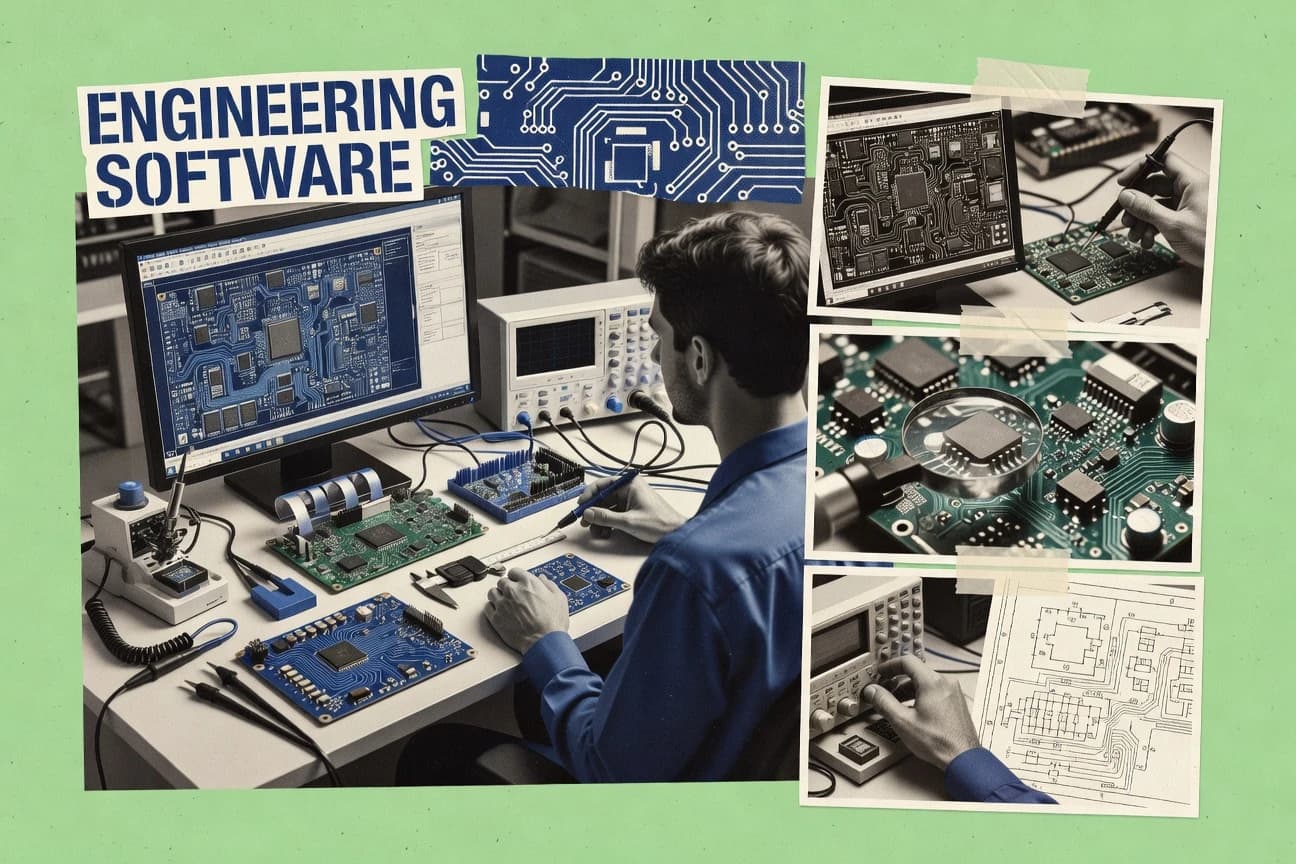
Manufacturing EngineeringTop 10 Best Electronics Engineering Software of 2026
Top 10 electronics engineering software ranking for circuit design and simulation, with comparisons of CircuitLab, LTspice, KiCad and other tools.

How we ranked these tools
Core product claims cross-referenced against official documentation, changelogs, and independent technical reviews.
Analyzed video reviews and hundreds of written evaluations to capture real-world user experiences with each tool.
AI persona simulations modeled how different user types would experience each tool across common use cases and workflows.
Final rankings reviewed and approved by our editorial team with authority to override AI-generated scores based on domain expertise.
Score: Features 40% · Ease 30% · Value 30%
Gitnux may earn a commission through links on this page — this does not influence rankings. Editorial policy
CircuitLab is the best overall pick for small teams that want repeatable schematic simulation and easy link-based design review, while LTspice is the cheapest entry point if you mainly need fast SPICE iteration and waveform checks, and KiCad fits teams who prefer a local ECAD workflow with solid rule checking and standard exports.
Editor’s top 3 picks
Three quick recommendations before you dive into the full comparison below — each one leads on a different dimension.
CircuitLab
Shareable circuit links that package schematic and simulation setup for consistent review.
Built for fits when small teams need repeatable schematic simulation and link-based design review..
LTspice
Editor pickUnified schematic and SPICE simulation loop with directive-driven controls and in-editor waveform probing.
Built for fits when analog teams need fast SPICE iteration from schematic capture to waveform review..
KiCad
Editor pickDesign rule checking runs against constraints during editing, reducing late-stage constraint drift before export.
Built for fits when teams need a local ECAD workflow with strong rule checking and standard export outputs..
Related reading
- Manufacturing EngineeringTop 10 Best Electronic Circuit Designer Software of 2026
- Automotive ServicesTop 10 Best Electronics Repair Shop Management Software of 2026
- Manufacturing EngineeringTop 10 Best Electrical Modeling Software of 2026
- Manufacturing EngineeringTop 10 Best Materials Selection Software of 2026
Comparison Table
Electronics engineering software shapes every handoff from schematic entry to simulation and PCB layout, which directly affects design verification time and error rates. This ranked list targets analysts and engineering operators who need concrete selection criteria across open and commercial toolchains, using decision tradeoffs around simulation depth, layout automation, and workflow integration rather than marketing claims.
CircuitLab
SMBCircuitLab provides browser-based schematic drawing and circuit simulation.
Shareable circuit links that package schematic and simulation setup for consistent review.
CircuitLab’s core workflow centers on schematic capture plus SPICE simulation, with simulation settings tied directly to the schematic elements. Results can be inspected in a way that maps back to circuit nodes and components, which reduces manual translation between a schematic and a simulator deck. Link-based sharing supports asynchronous review of both the circuit structure and the simulation configuration. This integration is valuable when teams need quick design iteration cycles rather than heavyweight design governance.
A practical tradeoff is that CircuitLab is less suited to deep PCB design rule checking workflows and manufacturing output pipelines than full ECAD systems. CircuitLab fits best for troubleshooting, topology exploration, and early validation of analog or mixed-signal circuits before committing to PCB layout. It also fits scenarios where stakeholders need a reproducible simulation artifact they can open without building a local simulation environment.
- +Tight schematic-to-simulation workflow reduces simulator deck translation
- +Interactive inspection of node voltages and currents supports rapid debugging
- +Link-based sharing preserves circuit structure and simulation configuration
- +Library-driven part placement speeds up common analog topologies
- –Limited coverage for deep printed circuit board layout and rule checking
- –Advanced SPICE control workflows can require manual setup discipline
- –High-frequency analysis breadth is narrower than specialized SI tools
- –Export paths are weaker for full manufacturing data generation
Lab engineers
Validate bias circuits quickly
Faster iteration on working points
Teaching teams
Grade homework with reproducible sims
Consistent grading artifacts
Show 2 more scenarios
Consultants
Explain designs with interactive evidence
Reduced back-and-forth explanations
Provide a shareable simulation view to support client discussions and changes.
Hardware startups
Prototype analog sections before layout
Fewer late-stage electrical surprises
Simulate early circuit variants to de-risk topology choices before PCB work begins.
Best for: Fits when small teams need repeatable schematic simulation and link-based design review.
More related reading
LTspice
vertical specialistLTspice is a free SPICE simulator for analog circuit analysis and switching regulator design.
Unified schematic and SPICE simulation loop with directive-driven controls and in-editor waveform probing.
LTspice pairs schematic capture with SPICE simulation so netlists are generated directly from the schematic workflow, which reduces version drift during iterative changes. It includes simulation control through directives on the schematic and supports standard analysis types used in analog debugging and verification. Its model handling and library structure are built around device-level SPICE models, which is a good fit for amplifier, regulator, and filter work.
A key tradeoff is that LTspice focuses on circuit-level simulation rather than full PCB workflow automation, so design rule checking and impedance control live outside the tool. LTspice is a strong fit for quick verification loops on analog topologies, like checking transient startup, load-step response, and gain roll-off before committing to layout.
- +Schematic-to-SPICE workflow supports rapid iterative debugging cycles
- +Waveform viewing and probing stay in the same editor context
- +Extensive analog-focused device model library supports common blocks
- +Works well for small-signal and transient checks across many topologies
- –Limited native coverage for PCB layout and rule checking workflows
- –Advanced automation is harder than script-driven ECAD suites
- –Model portability depends on SPICE dialect consistency across vendors
- –Large mixed-signal projects can become unwieldy without careful organization
Analog design engineers
Transient and gain verification for prototypes
Faster prototype troubleshooting
Hardware verification teams
Regression checks for circuit changes
More consistent behavior tracking
Show 2 more scenarios
Student and lab users
Hands-on SPICE learning and experiments
Quicker learning feedback
Build small analog circuits and validate waveforms across operating conditions.
Analog modeling specialists
Parameter tuning for device models
Better model fit
Adjust SPICE parameters and compare AC and transient responses to expectations.
Best for: Fits when analog teams need fast SPICE iteration from schematic capture to waveform review.
KiCad
SMBKiCad is an open-source suite for schematic capture, PCB layout, simulation, and design visualization.
Design rule checking runs against constraints during editing, reducing late-stage constraint drift before export.
KiCad covers the core ECAD loop with schematic capture, PCB layout, and constraint management that feeds design rule checking during editing. Board creation supports component library management workflows where footprints and symbols can be verified for compatibility before committing layout. Exports include standard manufacturing outputs for PCB fabs and assembly flows, which helps teams standardize downstream data. Integration stays local because projects are stored as files on disk, which simplifies offline work and version control for engineering teams.
A tradeoff appears in how advanced verification and analysis depends on external tool integration rather than a single built-in engine set. Signal integrity analysis, electromagnetic compatibility analysis, and thermal analysis typically require add-ons or external simulators, so deeper studies add workflow steps. KiCad fits best when the goal is to iterate quickly from schematic to routed PCB while maintaining traceability through a consistent on-disk project structure.
- +Tight schematic to PCB handoff with consistent project structure
- +Electrical and manufacturing design rule checking during layout edits
- +Manufacturing exports cover common PCB fab and assembly handoff formats
- +Local file-based workflow works well with version control and offline edits
- –Advanced signal integrity and EMC workflows rely on external tools
- –Complex automation needs scripting or add-ons beyond built-in GUI actions
- –Large component libraries can slow editing without library hygiene
- –Some model ecosystems require extra preparation for footprints and simulation
Small electronics teams
Iterate from schematic to PCB quickly
Fewer board re-spins
Hardware teams using Git
Track ECAD changes in version control
Clear design traceability
Show 1 more scenario
Product engineers validating circuits
Run early electrical checks with SPICE
Faster electrical validation cycles
Simulation hooks support early verification without leaving the ECAD workflow.
Best for: Fits when teams need a local ECAD workflow with strong rule checking and standard export outputs.
OrCAD X
enterpriseOrCAD X supports schematic design, PCB layout, constraint management, and cloud-connected engineering workflows.
OrCAD X’s design rule and electrical rule engines apply constraint logic across schematic-to-layout workflows with project-scoped configuration.
OrCAD X is Cadence’s ECAD suite for schematic capture, PCB layout, and rule-driven design checks within a tightly connected workflow. It supports electrical rule checking and design rule checking to catch netlist and layout constraint violations before export.
Its simulation and analysis options extend design intent from schematic into validation for signal behavior and manufacturability artifacts. Automation is centered on reusable configuration, design rule sets, and project-wide settings that reduce manual rework across releases.
- +Design rule checking and electrical rule checking cover many standard constraint classes.
- +Project-wide rule sets reduce repeat setup across schematic and PCB iterations.
- +Manufacturing export workflows align with common ECAD-to-fab handoffs.
- +Tight schematic to layout consistency reduces net and footprint drift.
- –Automation and extensibility depend on Cadence-specific integration patterns.
- –Advanced high-speed and analysis workflows require careful configuration discipline.
- –Library and footprint verification can slow teams with weak component data hygiene.
- –Project migration between organizations can be heavy when rule databases differ.
Best for: Fits when teams need consistent rule checking across schematic and PCB with controlled release processes.
Autodesk Fusion Electronics
SMBFusion Electronics combines schematic capture and PCB design with mechanical CAD in Autodesk Fusion.
Constraint and electronics design data propagation across schematic, PCB layout, and verification steps.
Autodesk Fusion Electronics takes design data from schematic capture through PCB layout and tracks requirements and constraints across the workflow. It supports electronics-specific rule checking and simulation-driven iteration inside an integrated authoring environment.
Fusion Electronics also connects ECAD output to manufacturing preparation workflows by generating industry file formats and exchanging netlists for downstream validation. It is oriented around a single workspace model that keeps component and constraint data consistent during revisions.
- +End-to-end electronics workflow keeps constraints and component data synchronized
- +Design rule checking focuses on electronics-specific PCB constraints
- +Simulation-friendly iteration supports design validation loops
- +Manufacturing-oriented exports support common PCB handoff paths
- –Advanced signal integrity and power integrity analysis can require extra configuration
- –Automation and API coverage is narrower than general Fusion modeling workflows
Best for: Fits when teams need schematic-to-layout consistency with electronics rules and fabrication file generation.
EasyEDA
SMBEasyEDA is a browser-based electronics design platform for schematics, PCB layouts, and manufacturing orders.
Tight coupling between schematic editing and immediate PCB changes with browser-native workflow
EasyEDA is an electronics design tool centered on fast schematic capture and PCB layout work with a browser-first workflow. It supports SPICE simulation for functional checks and provides a component and footprint ecosystem aimed at reducing import friction.
The project workflow emphasizes publishing and sharing designs through generated manufacturing outputs like Gerber and drill files. Integration depth is strongest through interchange formats and a web collaboration model rather than deep PLM or enterprise automation.
- +Browser-based schematic and PCB editing reduces setup friction
- +Built-in SPICE simulation supports iterative checks during design
- +Manufacturing output generation includes Gerber and drill artifacts
- +Component and footprint library browsing speeds reuse
- –Automation and API surface are limited for high-throughput design pipelines
- –Advanced signal integrity and EMC analysis coverage is not its core focus
- –Large design governance features like detailed audit logs are limited
- –Strict workflow control for multi-team reuse is less mature than enterprise ECAD
Best for: Fits when teams need quick ECAD iteration with web collaboration and basic simulation.
Altium Designer
enterpriseAltium Designer provides professional PCB design, schematic capture, simulation, and library management.
Unified PCB constraint system with project-level electrical rule enforcement across design edits.
Altium Designer differentiates itself through a tight, end-to-end authoring workflow that connects schematic capture, PCB layout, and verification inside one project. The design environment centers on rule-driven implementation with design rule checking and electrical rule checking tied to nets and footprints.
Altium Designer also supports simulation workflows through SPICE-based analysis and time-saving high-speed serial planning features for controlled routing. Manufacturing output and collaboration are supported through Gerber and ODB++ export plus component and footprint management tied to the project hierarchy.
- +Project-linked constraint management keeps PCB layout consistent with schematic intent
- +Electrical rule checking and design rule checking update with net changes
- +High-speed serial design tools support differential pair routing with impedance control
- +ODB++ and Gerber outputs integrate cleanly with fabrication handoff workflows
- –Large projects can slow down when rule sets and component variants grow
- –Deep workflow configuration requires discipline to avoid conflicting rule sources
- –Some advanced analysis depends on setup-heavy simulation projects
- –Workspace customization can increase onboarding time for new team members
Best for: Fits when engineers need one rules-driven workflow from schematic to PCB with fabrication outputs.
NI Multisim
educationNI Multisim provides interactive schematic capture and SPICE simulation for electronic circuits.
Instrument-style interactive measurement controls tightly integrated with SPICE runs directly on the schematic view.
NI Multisim pairs schematic capture with SPICE-based analysis so circuit edits and simulation results stay tightly coupled.
Interactive simulation and instrument-style measurement views support verification tasks that mirror how signals are checked on the bench.
Library management and netlist exchange support reuse and integration with other tools in electronics workflows.
- +Tight schematic-to-SPICE workflow reduces context switching during iterative design
- +Interactive probing supports measurement workflows without manual data wrangling
- +Mixed-signal simulation supports discrete plus analog circuit verification
- +Component library management supports reuse across multiple designs
- –Printed circuit board design rules and layout capabilities are not its primary strength
- –Advanced signal integrity style analysis depends on external tools or add-ons
- –Automation is limited compared with toolchains that expose full simulation orchestration APIs
- –Complex multi-project versioning needs process discipline to avoid netlist drift
Best for: Fits when circuit teams need schematic-driven SPICE simulation and instrument-style measurements for verification.
Proteus
vertical specialistProteus combines schematic design, microcontroller simulation, and PCB layout for electronic systems.
Interactive mixed-signal simulation tied directly to the schematic workspace, with signal probing during execution.
Proteus is used for schematic capture and SPICE-based circuit simulation, including interactive, probe-driven runs. It couples mixed-signal simulation with part libraries that support realistic component behavior and packaging details for many electronics projects.
PCB design is supported alongside simulation workflows, with design rule checking and rule constraints that help catch layout-related issues. Proteus is best suited when engineering teams want one toolchain that ties together schematic, simulation, and board preparation steps.
- +Interactive SPICE simulation with live signal probing during runs
- +Mixed-signal workflow links schematic changes to simulation outcomes
- +Integrated PCB authoring supports rule-driven layout checks
- +Part and footprint libraries cover many common component categories
- –Automation and API surface for external toolchains is limited
- –Complex, vendor-specific import workflows can require manual cleanup
- –High-speed signal integrity depth is not as extensive as SI-focused suites
- –Larger projects can feel slower when rebuilding simulation models
Best for: Fits when teams need schematic-driven simulation and PCB authoring in one workflow, with moderate automation needs.
Tinkercad Circuits
educationTinkercad Circuits provides browser-based circuit construction, Arduino simulation, and virtual component testing.
Breadboard-style wiring with instant, visual circuit checks designed for education workflows rather than production engineering.
Tinkercad Circuits is a browser-based electronics sandbox where wiring, components, and simple test workflows live in one place. It supports breadboard-style schematic capture and basic behavioral checks for educational circuits, including common logic and sensor setups.
The environment focuses on quick iteration rather than export-grade ECAD deliverables or deep electrical fidelity. SPICE simulation and PCB design rule workflows are not its core strength, which makes it better suited for learning and early concept verification.
- +Immediate visual wiring and component placement in-browser
- +Fast feedback for basic circuit operation and logic behavior
- +Low setup overhead for classroom and self-paced labs
- +Good starter path to breadboard thinking and troubleshooting
- –No workflow for PCB design rules or Gerber/ODB++ output
- –Limited simulation depth compared with full SPICE toolchains
- –Small parts of the workflow do not map to manufacturing-ready documentation
- –Advanced topics like constraint management and signal integrity analysis are out of scope
Best for: Fits when learners and small teams need quick circuit iteration without ECAD export requirements.
Conclusion
After evaluating 10 manufacturing engineering, CircuitLab stands out as our overall top pick — it scored highest across our combined criteria of features, ease of use, and value, which is why it sits at #1 in the rankings above.
Use the comparison table and detailed reviews above to validate the fit against your own requirements before committing to a tool.
How to Choose the Right electronics engineering software
This guide covers CircuitLab, LTspice, KiCad, OrCAD X, Autodesk Fusion Electronics, EasyEDA, Altium Designer, NI Multisim, Proteus, and Tinkercad Circuits for schematic capture, PCB authoring, and simulation workflows.
It focuses on integration depth from schematic to SPICE or PCB rule checking, plus automation and configuration realities that affect multi-step electronics engineering projects.
Electronics ECAD and simulation tools that connect schematics, verification, and board handoff
Electronics engineering software covers schematic capture and computer-aided design workflows that move from design intent into SPICE simulation or printed circuit board authoring. These tools help engineers validate circuit behavior, apply electrical and manufacturing constraints, and export board deliverables like Gerber output. KiCad represents one common practice path by keeping schematic capture, PCB layout, and design rule checking in a single local project workflow.
LTspice represents a complementary practice by focusing on an iterative schematic-to-SPICE loop with waveform probing in the same editor context for analog analysis. Tools like these are used by circuit designers, PCB layout engineers, and small teams that need repeatable design review and faster error discovery.
Constraint logic, simulation coupling, and handoff artifacts that determine real engineering throughput
Electronics tools must keep schematic intent consistent with either simulation inputs or PCB constraint enforcement, because drift between steps creates rework. CircuitLab and LTspice excel at that coupling for SPICE-driven debugging, while KiCad, OrCAD X, and Altium Designer emphasize rule engines during layout edits.
For evaluation, the most discriminating signals are how constraint logic is applied across workflows, how simulation runs attach to the schematic view, and how reliably outputs fit fabrication and collaboration paths. Browser-first workflows like EasyEDA and learning-focused tools like Tinkercad Circuits also change what “engineering-ready” deliverables look like.
Shareable schematic-plus-simulation review packaging
CircuitLab packages schematic and simulation setup into link-based sharing so later reviewers see the same circuit configuration and results context. This matters for teams that do design reviews by passing a link rather than rebuilding a simulator deck from scratch, and it directly reduces translation effort during debugging.
Unified schematic-to-SPICE loop with in-editor probing controls
LTspice keeps waveform viewing and probing in the same editor context as the schematic, which supports fast iterative debugging cycles. NI Multisim also ties SPICE runs to the schematic view through instrument-style interactive measurement controls, which is valuable for measurement-style verification rather than batch simulation.
Constraint logic enforced during editing with project-scoped rule application
KiCad runs design rule checking against constraints during editing, which reduces late-stage constraint drift before export. OrCAD X extends the same idea by applying both design rule checking and electrical rule checking engines across schematic-to-layout workflows with project-scoped configuration.
Electronics and mechanical data propagation across the authoring workflow
Autodesk Fusion Electronics propagates electronics constraints and component data across schematic, PCB layout, and verification steps inside one integrated environment. This matters when mechanical and electronics revisions must stay synchronized to avoid mismatches during board iteration and manufacturing preparation.
Project hierarchy constraint consistency and fabrication handoff outputs
Altium Designer uses a unified PCB constraint system that enforces project-level electrical rules across design edits. It also supports export paths like ODB++ and Gerber while keeping constraint updates tied to net changes, which helps teams keep fabrication files aligned with schematic intent.
Browser-native ECAD workflow that couples schematic edits to PCB changes
EasyEDA couples schematic editing to immediate PCB changes using a browser-first workflow, which reduces friction for small teams iterating quickly. Proteus similarly links schematic changes to mixed-signal simulation outcomes and supports interactive probing during execution, but it offers more depth around mixed-signal simulation than basic web collaboration paths.
Select by coupling style: schematic-first SPICE iteration, rule-driven ECAD, or browser and learning workflows
A practical selection starts with the workflow coupling needed for the next engineering milestone. If the milestone is iterative analog debugging, tools like LTspice and NI Multisim reduce context switching by keeping probing and measurements tied to the schematic view.
If the milestone is getting to reliable board constraints and manufacturing handoff, tools like KiCad, OrCAD X, and Altium Designer apply constraint logic during layout edits and keep electrical checks connected to net and footprint relationships. Browser-first and learning tools like EasyEDA and Tinkercad Circuits shift the target to fast iteration rather than full production deliverables.
Start from the primary verification loop: SPICE-only iteration vs schematic-to-board rule enforcement
Choose LTspice for an analog-focused loop that runs SPICE analyses from a tightly integrated schematic interface with directive-driven controls and in-editor waveform probing. Choose KiCad, OrCAD X, or Altium Designer when the primary loop is electrical rule checking and design rule checking during PCB edits, because constraints update with net and layout changes rather than after-the-fact export checks.
Pick the integration depth for collaboration and review artifacts
Choose CircuitLab when design review is link-based and must preserve circuit setup for later inspection, since the shareable circuit links package schematic and simulation configuration together. Choose EasyEDA when collaboration relies on browser-native editing and generating manufacturing outputs like Gerber and drill artifacts directly from the web workflow.
Match the tool’s automation shape to the engineering pipeline
Choose OrCAD X when automation and configuration are centered on reusable design rule sets and project-wide settings, because constraint logic stays tied to a controlled release process. Choose KiCad when automation can tolerate scripting around GUI-based actions, because complex automation for pipelines needs scripting or add-ons beyond built-in GUI actions.
Decide whether mixed-signal and instrument-style workflows matter more than deep SI/EMC.
Choose NI Multisim if instrument-style interactive measurement controls must run directly on the schematic with mixed-signal simulation support. Choose Proteus when mixed-signal simulation tied to the schematic workspace with live signal probing is the priority, since it also supports PCB authoring with rule constraints but does not target the deepest high-speed signal integrity depth.
Choose the board deliverable readiness level for downstream manufacturing.
Choose Altium Designer when fabrication handoff needs ODB++ and Gerber outputs that stay connected to project-level electrical rule enforcement. Choose KiCad when local file-based workflows and standard Gerber exports are the baseline, since design rule checking during editing reduces late constraint drift before manufacturing export.
Electronics tool selection by team role, workflow stage, and required deliverables
Different tool classes map to different roles in electronics engineering and different stages of the design-to-fab pipeline. CircuitLab and LTspice fit circuit teams who prioritize repeatable schematic simulation and fast waveform inspection.
KiCad, OrCAD X, and Altium Designer fit teams that must enforce electrical and manufacturing rules while building fabrication-ready PCB deliverables. EasyEDA, Proteus, and Autodesk Fusion Electronics serve specific integration needs like web collaboration, mixed-signal plus board authoring, or electronics-to-mechanical propagation.
Small teams doing repeatable schematic simulation and link-based design review
CircuitLab fits this segment because shareable circuit links package schematic and simulation setup so reviewers see consistent circuit configuration and results context without rebuilding simulation decks.
Analog engineers optimizing iterative waveform inspection cycles
LTspice fits because it keeps schematic, SPICE simulation, and in-editor waveform probing in one interface with an analog-focused device model library for transient and AC work. NI Multisim fits when measurement-style interactive controls must be tied to SPICE runs directly on the schematic view.
PCB teams that must apply constraint engines during layout edits and export standard fabrication outputs
KiCad fits because design rule checking runs against constraints during editing and manufacturing exports cover common PCB fab and assembly handoff formats. OrCAD X fits when project-scoped design rule sets and electrical rule engines must enforce constraint logic across schematic-to-layout workflows for controlled releases.
Engineers needing unified project constraints plus advanced serial planning and fabrication outputs
Altium Designer fits because it uses a unified PCB constraint system that enforces project-level electrical rules across edits and supports differential pair routing with impedance control. It also exports ODB++ and Gerber in workflows tied to project hierarchy.
Teams that prioritize schematic-to-mechanical-to-electronics propagation or web and education workflows
Autodesk Fusion Electronics fits when constraint and electronics design data propagation must stay consistent across schematic, PCB layout, and verification steps inside an integrated environment. EasyEDA fits teams that want browser-first schematic and PCB editing with immediate coupling and Gerber and drill artifact generation, while Tinkercad Circuits fits learners needing breadboard-style wiring with quick visual circuit checks and no manufacturing-grade export requirements.
Where electronics engineering software selection commonly fails in real projects
Selection mistakes usually show up when the chosen tool’s workflow coupling does not match the next engineering milestone. Many teams expect deep PCB layout rule enforcement from SPICE-first tools, which leaves constraint validation to later steps.
Other teams pick a full ECAD suite but then underestimate the governance overhead created by rule databases, component variants, and automation constraints.
Assuming a SPICE simulator will cover PCB design rules and layout verification
LTspice and NI Multisim focus on schematic-driven SPICE iteration and probing, so PCB layout rule checking is not their primary strength. KiCad and OrCAD X fit PCB constraint enforcement needs because design rule checking runs during editing and electrical rule engines apply constraint logic across schematic-to-layout workflows.
Building a workflow that depends on deep SI and EMC inside a tool that targets general ECAD or schematic-to-simulation only
KiCad and EasyEDA both rely on external tooling for advanced signal integrity and EMC workflows, which can stall high-speed design iteration. Altium Designer supports time-saving high-speed serial planning with controlled routing features like differential pair impedance control, which is closer to high-speed workflows than basic rule checking alone.
Overlooking how project rule configuration and component data hygiene affect automation outcomes
OrCAD X automation and extensibility depend on Cadence-specific integration patterns and project-scoped configuration discipline, so weak library and footprint verification slows layout work. Altium Designer also slows large projects when rule sets and component variants grow, so component library hygiene and variant control matter for throughput.
Expecting full manufacturing-grade export and governance from browser-first or education-focused tools
EasyEDA generates manufacturing outputs like Gerber and drill files but has limited automation and API surface for high-throughput pipelines, and deep governance features like detailed audit logs are limited. Tinkercad Circuits has no workflow for PCB design rules or Gerber and ODB++ output, so it cannot replace ECAD tools for production documentation.
How We Selected and Ranked These Tools
We evaluated CircuitLab, LTspice, KiCad, OrCAD X, Autodesk Fusion Electronics, EasyEDA, Altium Designer, NI Multisim, Proteus, and Tinkercad Circuits using three criteria tied to engineering workflow reality. Each tool received a score for features coverage, a score for ease of use in its main authoring loop, and a score for value in how those features translate into productive iteration. Features carries the most weight at 40 percent, while ease of use and value each account for 30 percent.
CircuitLab set itself apart by combining schematic drawing and SPICE simulation inside one workspace with shareable circuit links that package schematic and simulation setup for consistent review, which lifted it across the features and workflow integration criteria more than tools that separate simulation from review or that focus on PCB deliverables without that link-based consistency.
Frequently Asked Questions About electronics engineering software
How do CircuitLab and NI Multisim handle schematic-driven SPICE simulation workflows?
Which tool supports a unified electrical rules to PCB layout loop with project-scoped configuration?
When does KiCad’s local ECAD workflow outperform browser-first ECAD tools like EasyEDA?
What tradeoff appears when using link-based sharing in CircuitLab instead of full ECAD authoring with Altium Designer or OrCAD X?
How do LTspice and Proteus differ for mixed-signal verification when probing circuits?
Where do data interchange paths and manufacturing outputs diverge between Autodesk Fusion Electronics and KiCad?
What breaks if a team relies on quick browser iteration from Tinkercad Circuits for production-grade PCB delivery?
How do automation and configuration differ between OrCAD X and Autodesk Fusion Electronics for repeated design rule checks?
When should engineers choose EasyEDA over KiCad for component and footprint import workflows?
Tools reviewed
Primary sources checked during evaluation.
Referenced in the comparison table and product reviews above.
Keep exploring
Comparing two specific tools?
Software Alternatives
See head-to-head software comparisons with feature breakdowns, pricing, and our recommendation for each use case.
Explore software alternatives→In this category
Manufacturing Engineering alternatives
See side-by-side comparisons of manufacturing engineering tools and pick the right one for your stack.
Compare manufacturing engineering tools→FOR SOFTWARE VENDORS
Not on this list? Let’s fix that.
Our best-of pages are how many teams discover and compare tools in this space. If you think your product belongs in this lineup, we’d like to hear from you—we’ll walk you through fit and what an editorial entry looks like.
Apply for a ListingWHAT THIS INCLUDES
Where buyers compare
Readers come to these pages to shortlist software—your product shows up in that moment, not in a random sidebar.
Editorial write-up
We describe your product in our own words and check the facts before anything goes live.
On-page brand presence
You appear in the roundup the same way as other tools we cover: name, positioning, and a clear next step for readers who want to learn more.
Kept up to date
We refresh lists on a regular rhythm so the category page stays useful as products and pricing change.