GITNUXSOFTWARE ADVICE
Manufacturing EngineeringTop 9 Best Electronic Schematic Drawing Software of 2026
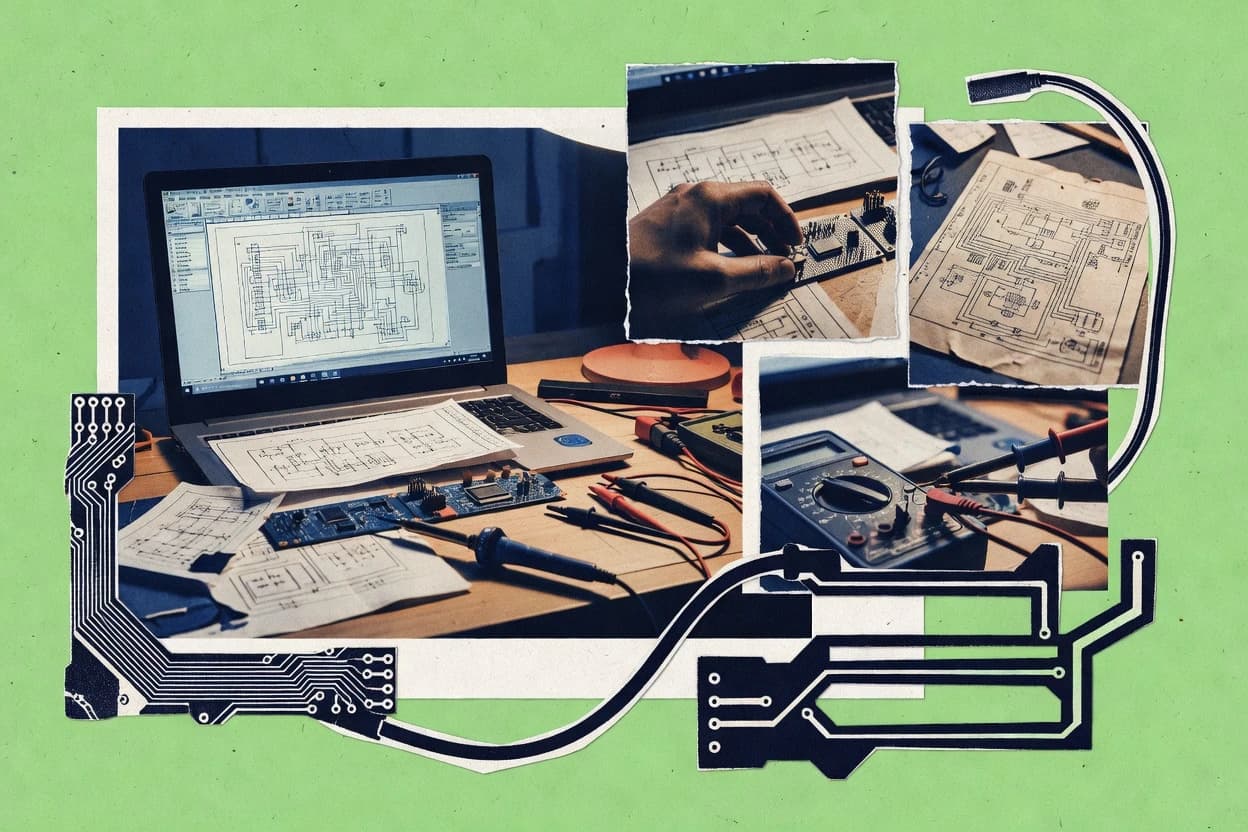
Compare the top 10 Electronic Schematic Drawing Software tools for fast drafting and clean schematics. See the ranked picks now.

How we ranked these tools
Core product claims cross-referenced against official documentation, changelogs, and independent technical reviews.
Analyzed video reviews and hundreds of written evaluations to capture real-world user experiences with each tool.
AI persona simulations modeled how different user types would experience each tool across common use cases and workflows.
Final rankings reviewed and approved by our editorial team with authority to override AI-generated scores based on domain expertise.
Score: Features 40% · Ease 30% · Value 30%
Gitnux may earn a commission through links on this page — this does not influence rankings. Editorial policy
Editor’s top 3 picks
Three quick recommendations before you dive into the full comparison below — each one leads on a different dimension.
Altium Designer
Integrated schematic capture tied to PCB design rules and live design synchronization
Built for teams shipping complex PCB designs needing disciplined schematic-to-layout consistency.
Cadence OrCAD PCB Designer
Editor pickConnectivity-driven design linking from schematic nets to PCB layout
Built for teams needing schematic-to-board workflow integration for complex electronics.
Siemens EDA (Xpedition Enterprise)
Editor pickEnd-to-end schematic-to-layout design integration with enterprise project synchronization
Built for enterprises building large PCB designs with end-to-end schematic-to-layout integration.
Related reading
Comparison Table
This comparison table evaluates electronic schematic drawing software used for capturing circuit diagrams and managing design data across common PCB workflows. It compares tools such as Altium Designer, Cadence OrCAD PCB Designer, Siemens EDA Xpedition Enterprise, Autodesk Fusion Electronics, and KiCad on key factors including schematic features, PCB integration, and typical deployment models. Readers can use the results to narrow down options that match specific design complexity, collaboration needs, and toolchain constraints.
Altium Designer
integrated CADAltium Designer provides an integrated schematic capture and PCB design workflow with schematic rules checking, library management, and board-level electronics design.
Integrated schematic capture tied to PCB design rules and live design synchronization
Altium Designer stands out with its single, tightly integrated EDA workflow from schematic capture to PCB layout. It provides rule-driven schematic design with robust component management and hierarchical reuse for complex projects.
Native support for electronics libraries and publication-grade documentation helps teams generate schematics that match manufacturing intent. Tight back-annotation and consistency checks reduce schematic-to-layout mismatches during board development.
- +Seamless schematic-to-PCB connectivity with constraint propagation
- +Powerful hierarchical design with reusable sheets
- +Rules-based validation catches schematic and connectivity issues
- +Strong component library management with parametric models
- +Comprehensive documentation outputs from the design database
- –Steeper learning curve than lightweight schematic tools
- –Heavy projects can stress workstation resources
- –Workspace customization takes time for new teams
- –Library setup and governance require ongoing maintenance
- –Schematic-only use still pulls full PCB workflow
Best for: Teams shipping complex PCB designs needing disciplined schematic-to-layout consistency
Cadence OrCAD PCB Designer
PCB-focusedCadence OrCAD PCB Designer supports schematic capture and PCB layout with design rule checks and manufacturing-focused electronics data preparation.
Connectivity-driven design linking from schematic nets to PCB layout
Cadence OrCAD PCB Designer focuses on schematic capture that links directly into PCB layout workflows for tight design iteration. It supports hierarchical schematic design, extensive component part libraries, and connectivity-driven netlist creation.
The tool provides DRC-oriented design checks that help catch electrical and layout rule issues before fabrication data is finalized. Advanced routing, constraint handling, and export-ready outputs make it practical for complete electronic design from symbol creation to board output.
- +Schematic capture connects cleanly to PCB layout through netlist-driven workflow
- +Hierarchical schematics support large designs with structured organization
- +Strong constraint and rule checking reduces electrical and layout surprises
- +Robust libraries and part management speed symbol and net assignments
- –Setup complexity increases for users who need quick schematic-only workflows
- –Library management can be cumbersome without clear naming and version discipline
- –Deep PCB rule tuning requires time to match specific manufacturing requirements
Best for: Teams needing schematic-to-board workflow integration for complex electronics
Siemens EDA (Xpedition Enterprise)
enterprise EDASiemens EDA Xpedition Enterprise delivers schematic-driven electronics design with advanced constraint management and collaboration for complex manufacturing projects.
End-to-end schematic-to-layout design integration with enterprise project synchronization
Siemens EDA Xpedition Enterprise stands out with tightly integrated schematic-to-layout workflows for complex PCB design environments. It supports schematic capture with hierarchical design management, symbol reuse, and net connectivity consistency checks across documents.
The tool emphasizes collaborative engineering by enabling controlled project data handling and design synchronization workflows across distributed teams. It also integrates with Siemens implementation flows, which streamlines handoff from schematic generation to downstream verification and manufacturing preparation.
- +Hierarchical schematic capture with consistent net connectivity checks
- +Tight schematic-to-layout workflow integration across Siemens design flows
- +Project data management supports team-based design synchronization
- +Reusable symbols and libraries accelerate schematic construction
- –Steeper setup learning curve for full enterprise workflow configuration
- –Less flexible for standalone schematic-only use without layout integration
- –Complex projects require disciplined library and hierarchy governance
Best for: Enterprises building large PCB designs with end-to-end schematic-to-layout integration
Autodesk Fusion Electronics
cloud CADAutodesk Fusion Electronics provides schematic capture and PCB design tools aimed at producing fabrication-ready electronics layouts and outputs.
Automatic schematic-to-PCB component and connection propagation across the same project
Autodesk Fusion Electronics stands out by blending schematic capture with project-managed PCB design inside the Autodesk ecosystem. The workflow connects a schematic to a PCB layout so component changes can propagate through the design chain.
It supports hierarchical libraries and symbol-to-footprint mapping so electronic parts stay consistent across revisions. It also includes rule-aware wiring and exportable design outputs for downstream manufacturing preparation.
- +Schematic-to-PCB link keeps component placement and wiring aligned across the design
- +Library-driven symbols and footprints reduce mismatch errors during revisions
- +Hierarchical organization supports complex projects with reusable subcircuits
- +Rule-aware wiring guidance speeds up initial electrical connections
- +Integration with Autodesk workflows supports smooth data handoff
- –Schematic workflows feel less specialized than dedicated EDA-only tools
- –Advanced constraint and validation depth may lag top-tier EDA suites
- –Large hierarchies can slow interactive editing on complex projects
- –Some specialized schematic views and reporting are less extensive than incumbents
Best for: Teams needing connected schematic and PCB workflows within Autodesk design tooling
KiCad
open sourceKiCad offers schematic capture and PCB layout with a free toolchain, electrical rule checks, and generation of manufacturing outputs from the same project data.
Hierarchical schematic sheets with ERC-driven design rule validation
KiCad stands out with a unified workflow for schematic capture and PCB layout in one open toolchain. It supports hierarchical schematics, reusable symbol libraries, and ERC checks that catch connectivity and power issues before export.
Core drawing features include place, wire, label, and bus tools with annotation management for consistent reference designators. Export paths cover standard PCB formats and generate outputs for downstream fabrication and simulation workflows.
- +Hierarchical sheets support complex designs with clear reuse patterns
- +ERC highlights missing connections and electrical rule violations
- +Annotation tools keep reference designators consistent across edits
- +Rich symbol and footprint libraries with project-specific custom additions
- –Learning the library and field system takes time for new users
- –Editing large sheets can feel slower than some commercial EDA tools
- –Advanced automation often requires manual schematic structuring discipline
Best for: Open-source electronics teams needing reliable schematics with ERC and PCB handoff
Zuken CR-8000
schematic suiteZuken CR-8000 enables engineering teams to create and manage electrical schematics with structured design data for large manufacturing environments.
Controlled electrical schematics with enforced design rules and structured project documentation
Zuken CR-8000 stands out with deep integration into industrial electrical design workflows and established component library usage. Core capabilities include creating electrical schematics, managing document structure, and enforcing controlled design rules across projects.
It supports signal and data connectivity planning using net and terminal concepts, which helps keep drawings consistent as designs evolve. Collaboration is handled through structured project management features tied to engineering change processes.
- +Strong electrical schematic data model with nets and terminals
- +Document hierarchy tools help manage large multi-sheet designs
- +Design-rule enforcement reduces inconsistent drawing practices
- +Ecosystem workflow alignment for industrial electrical engineering
- +Library-driven symbols and parts speed standardized schematic creation
- –Interface can feel complex for small schematic-only projects
- –Learning curve is steep for rule sets and project control
- –Deep workflow integration can slow ad-hoc drawing updates
- –Customization often requires process understanding beyond drawing basics
- –UI navigation can be cumbersome in very large document sets
Best for: Industrial teams producing rule-driven electrical schematics across multi-sheet projects
Mentor Graphics PADS
PCB-focusedMentor PADS supports schematic entry and PCB design with rule checking and design documentation outputs used in manufacturing engineering.
Netlist-driven schematic-to-PCB workflow that maintains connectivity integrity
Mentor Graphics PADS stands out for its tight integration between schematic entry and PCB design workflows. It supports structured component libraries, robust symbol and footprint management, and netlist-driven connectivity for electronics drafting.
The tool provides interactive editing, design rule aware handling of connectivity, and project-level organization for multi-sheet schematics. It is geared toward teams that need reliable schematic capture linked directly to downstream PCB layout tasks.
- +Strong netlist-to-PCB connectivity reduces schematic-to-layout mismatches
- +Library management supports consistent symbols and footprints across projects
- +Multi-sheet schematics with organized hierarchy improves large design readability
- –Workflow is oriented toward PCB-centric users, not schematic-only drafting
- –Interface complexity can slow initial setup for new projects
- –Library customization requires disciplined naming and configuration control
Best for: PCB-focused teams needing dependable schematic-to-layout integration and library consistency
EPLAN Electric P8
industrial E-PlanEPLAN Electric P8 supports industrial electrical schematic drawing with structured data handling and project management for manufacturing engineering.
Automated terminal allocation and cable list generation from schematic connectivity data
EPLAN Electric P8 centers on electrical schematic creation with tight electrical rules checking and automatic cross-referencing between devices, terminals, and wiring. The software combines schematic design, terminal plan generation, and cable and wire lists using a shared data model for consistent documentation.
Strong macro and template support accelerates repetitive circuitry and standard document layouts across large projects. Connectivity and allocation tools help maintain traceable connections through detailed electrical data rather than drawing-only edits.
- +Electrical rule checking reduces inconsistent terminals, connections, and references
- +Shared data model keeps schematic, terminals, and wiring lists synchronized
- +Macro and template system speeds standardized circuit documentation
- +Robust cross-referencing supports traceability across project documents
- –Complex configuration and data modeling increases setup effort
- –Large projects can feel heavy without disciplined project structuring
- –User onboarding can be slow for terminal and wiring workflows
- –Interface density can make simple edits harder to find
Best for: Engineering teams producing disciplined electrical documentation with rules-driven automation
SmartDraw
diagrammingSmartDraw provides template-driven electrical and schematic diagram drawing capabilities for manufacturing documentation workflows.
Circuit diagram templates with symbol library layout for rapid schematic drafting
SmartDraw differentiates itself with fast diagram creation using built-in templates and smart shape libraries. It supports electronic schematic drawing through dedicated circuit diagram symbols and wiring-style layout controls.
Collaboration and export workflows help move schematics into documentation or presentations. Its focus stays on drawing and organization rather than deep simulation or PCB-specific design flows.
- +Extensive template and symbol libraries for schematic-style circuit diagrams
- +Clean alignment tools speed up wiring and component layout
- +Exports support sharing schematics in common document and image formats
- +Library-driven editing reduces manual symbol setup
- –Limited support for circuit simulation and electrical verification
- –Advanced PCB layout features are not the primary workflow focus
- –Schematic-to-netlist automation is not a core capability
- –Large custom symbol creation can feel less structured than CAD tools
Best for: Teams producing clear schematics for documentation and presentations, not PCB manufacturing.
How to Choose the Right Electronic Schematic Drawing Software
This buyer's guide covers how to choose electronic schematic drawing software for real PCB, electrical, and documentation workflows using Altium Designer, Cadence OrCAD PCB Designer, Siemens EDA Xpedition Enterprise, Autodesk Fusion Electronics, KiCad, Zuken CR-8000, Mentor Graphics PADS, EPLAN Electric P8, and SmartDraw. It explains what specific capabilities matter, which tools best match different teams, and which mistakes commonly break schematic-to-layout or documentation consistency. It also provides a decision framework that maps tool capabilities to project risks like rule violations, library mismatches, and connectivity confusion.
What Is Electronic Schematic Drawing Software?
Electronic schematic drawing software creates circuit diagrams that represent components, pins, nets, hierarchy, and electrical relationships that later feed PCB layout or manufacturing documentation. It prevents errors by linking schematic connectivity to constraint or rules checks, and it helps teams keep component symbols and reference designators consistent across revisions. In practice, Altium Designer and Cadence OrCAD PCB Designer tie schematic capture into PCB design so schematic nets and connectivity drive PCB layout. KiCad supports the same schematic-to-PCB handoff pattern with ERC checks and unified project data for manufacturing outputs.
Key Features to Look For
The best tools reduce electrical and schematic-to-layout mismatches by combining connectivity-aware design rules, controlled libraries, and hierarchy that scales to multi-sheet projects.
Integrated schematic-to-PCB consistency with rule enforcement
Look for tight linkage so schematic connectivity and constraints propagate into PCB layout tasks. Altium Designer excels with constraint propagation and live design synchronization between schematic capture and PCB rules. Mentor Graphics PADS and Cadence OrCAD PCB Designer also maintain connectivity integrity using netlist-driven workflows that reduce schematic-to-layout mismatches.
Connectivity-driven netlist and synchronization workflows
Connectivity-driven workflows ensure the net assignments in the schematic become the authoritative connectivity model for PCB design or downstream electrical documentation. Cadence OrCAD PCB Designer highlights connectivity-driven design linking from schematic nets to PCB layout. Siemens EDA Xpedition Enterprise and Autodesk Fusion Electronics further emphasize schematic-to-layout design synchronization and component and connection propagation within the same project chain.
Hierarchical schematics that scale across multi-sheet designs
Hierarchy makes complex systems readable and reusable, and it prevents edits in one sheet from breaking global connectivity intent. Altium Designer provides powerful hierarchical design with reusable sheets. KiCad also supports hierarchical schematic sheets with ERC-driven validation, and Zuken CR-8000 adds document hierarchy tools for large multi-sheet electrical sets.
Electrical rule checks and ERC for missing connections and violations
ERC catches electrical mistakes like missing connections and power issues before export or handoff. KiCad provides ERC highlights for connectivity and electrical rule violations. Altium Designer, Cadence OrCAD PCB Designer, and EPLAN Electric P8 add rule-aware validation and electrical rule checking to reduce inconsistent terminals, connections, and references.
Library management that preserves symbol-to-footprint or document mapping
Reliable libraries prevent mismatches between schematic components and PCB footprints or manufacturing records. Altium Designer emphasizes strong component library management with parametric models. Autodesk Fusion Electronics and Mentor Graphics PADS also focus on symbol-to-footprint mapping and robust symbol and footprint management tied to the schematic-to-PCB workflow.
Automated electrical documentation outputs from schematic connectivity
Automations that generate terminal plans, cable lists, and cross-references reduce manual transcription errors. EPLAN Electric P8 generates terminal allocation and cable list generation from schematic connectivity data using a shared data model for synchronized schematic, terminals, and wiring lists. Zuken CR-8000 similarly enforces controlled design rules with nets and terminals to keep drawings consistent as designs evolve.
How to Choose the Right Electronic Schematic Drawing Software
A practical selection framework maps the tool’s connectivity, rule checking, library governance, and integration depth to the exact schematic-to-layout or documentation outcomes needed.
Match the tool to the required output chain
If the deliverable is a board that must stay consistent with the schematic, prioritize integrated schematic-to-PCB tools like Altium Designer, Cadence OrCAD PCB Designer, Mentor Graphics PADS, and Siemens EDA Xpedition Enterprise. If the deliverable is electrical documentation with terminals, wiring lists, and traceability, choose EPLAN Electric P8 or Zuken CR-8000 because they build a shared data model and generate terminal and cable outputs from connectivity.
Verify schematic-to-connector synchronization behavior
For PCB projects, require a connectivity-driven workflow where schematic nets drive PCB layout connectivity. Cadence OrCAD PCB Designer and Mentor Graphics PADS emphasize netlist-driven connectivity to reduce mismatches. Autodesk Fusion Electronics provides automatic schematic-to-PCB component and connection propagation within the same project so revisions remain aligned.
Check rule checking depth for the mistakes likely in the project
If teams frequently miss wiring or power connections, KiCad’s ERC highlights missing connections and electrical rule violations during the schematic stage. If teams need disciplined electrical constraints across the whole board design, Altium Designer and Cadence OrCAD PCB Designer provide rules-based validation that catches schematic and connectivity issues. If teams need electrical documentation consistency with terminals and cross-references, EPLAN Electric P8 uses electrical rules checking and synchronized references.
Assess library governance and revision stability
If components change often, choose tools that maintain symbol-to-footprint mapping or parametric component models. Altium Designer’s component library management with parametric models targets stable symbol reuse and consistent manufacturing intent. Autodesk Fusion Electronics and Mentor Graphics PADS emphasize symbol and footprint mapping so footprint mismatches do not creep in during revisions.
Plan for hierarchy and collaboration needs
For large multi-sheet systems, select tools with hierarchical design that remains editable and consistent across documents. Altium Designer and KiCad support hierarchical schematics and reusable sheets, while Zuken CR-8000 and EPLAN Electric P8 add document hierarchy and structured project management for controlled engineering changes. For enterprises coordinating distributed teams, Siemens EDA Xpedition Enterprise adds controlled project data handling and design synchronization workflows across distributed environments.
Who Needs Electronic Schematic Drawing Software?
Different projects need different levels of schematic intelligence, from documentation-first diagramming to board-grade schematic-to-layout integrity and rule automation.
Teams shipping complex PCB designs that demand disciplined schematic-to-layout consistency
Altium Designer is the best match because it provides an integrated schematic capture workflow tied to PCB design rules with live design synchronization. Cadence OrCAD PCB Designer and Mentor Graphics PADS also fit this audience because both use connectivity-driven netlist workflows that reduce schematic-to-layout surprises.
Teams needing schematic-to-board workflow integration for complex electronics with structured organization
Cadence OrCAD PCB Designer suits these teams because it supports hierarchical schematics and performs DRC-oriented checks that catch electrical and layout rule issues early. Autodesk Fusion Electronics also fits teams working inside Autodesk workflows because it propagates component changes and maintains schematic-to-PCB link integrity.
Enterprises building large PCB designs across synchronized engineering teams
Siemens EDA Xpedition Enterprise targets this group with end-to-end schematic-to-layout integration and enterprise project synchronization. It also supports hierarchical schematic capture with consistent net connectivity checks across documents for controlled project data handling.
Industrial and electrical engineering teams producing rule-driven multi-document electrical documentation
EPLAN Electric P8 fits engineering teams that need terminals, cable lists, and cross-referencing generated from schematic connectivity using a shared data model. Zuken CR-8000 also matches industrial teams because it enforces controlled electrical schematics with nets and terminals plus structured project documentation for large multi-sheet sets.
Common Mistakes to Avoid
Common failures come from choosing a tool that focuses on drawing speed rather than connectivity integrity, or from underestimating library governance and rule configuration effort for large designs.
Treating schematic diagrams as standalone drawings without connectivity integration
SmartDraw is strong for template-driven circuit diagrams for documentation and presentations, but it does not focus on schematic-to-netlist automation or PCB manufacturing handoff. For board-grade work, Altium Designer and Cadence OrCAD PCB Designer connect schematic nets to PCB rules so connectivity intent remains intact.
Ignoring rule checking and ERC depth until after export
KiCad provides ERC highlights for missing connections and electrical rule violations, so deferring validation wastes iteration cycles later. Altium Designer, Cadence OrCAD PCB Designer, and EPLAN Electric P8 add rules-based or electrical rule checking during design so electrical and connectivity issues are caught before fabrication data finalization.
Underestimating library setup and naming discipline for complex projects
Altium Designer requires ongoing library setup and governance maintenance, and Cadence OrCAD PCB Designer can be cumbersome without clear naming and version discipline. Mentor Graphics PADS and Autodesk Fusion Electronics also depend on consistent symbol-to-footprint mapping so disciplined library configuration prevents revision drift.
Using an enterprise or electrical-control workflow when the project needs ad-hoc schematic updates
Zuken CR-8000 and EPLAN Electric P8 enforce controlled electrical rules and structured project documentation, which can feel heavy for ad-hoc drawing updates. KiCad and Altium Designer can be faster choices for schematic-first iterations when the primary need is hierarchical schematics plus ERC-driven validation and PCB handoff.
How We Selected and Ranked These Tools
We evaluated every tool using three sub-dimensions with fixed weights: features at 0.4, ease of use at 0.3, and value at 0.3. The overall rating is computed as the weighted average with overall = 0.40 × features + 0.30 × ease of use + 0.30 × value. Altium Designer separated itself from lower-ranked options through feature breadth and integration depth that directly connect schematic capture to PCB design rules using live design synchronization, constraint propagation, and robust hierarchical reuse. This combination tightened schematic-to-layout consistency and improved engineering outcomes by reducing connectivity and design-rule mismatches before board development.
Frequently Asked Questions About Electronic Schematic Drawing Software
Which electronic schematic drawing tools provide the strongest schematic-to-PCB connectivity workflow?
How do Altium Designer, KiCad, and Autodesk Fusion Electronics handle hierarchical schematics and reuse?
What design-rule checks are available directly at the schematic stage in KiCad and OrCAD?
Which tools are best suited for large multi-sheet industrial electrical documentation?
How do EPLAN Electric P8 and Zuken CR-8000 manage terminals, wiring structures, and documentation outputs?
Which software options support team collaboration and controlled project data handling?
What is the practical difference between deep electronics design tools and diagram-focused tools like SmartDraw?
How do these tools keep component footprints consistent across schematic revisions?
What common schematic capture problems do the listed tools help mitigate?
Which toolchain fits best for users already embedded in a specific ecosystem like Autodesk or Siemens?
Conclusion
After evaluating 9 manufacturing engineering, Altium Designer stands out as our overall top pick — it scored highest across our combined criteria of features, ease of use, and value, which is why it sits at #1 in the rankings above.
Use the comparison table and detailed reviews above to validate the fit against your own requirements before committing to a tool.
Tools reviewed
Primary sources checked during evaluation.
Referenced in the comparison table and product reviews above.
Keep exploring
Comparing two specific tools?
Software Alternatives
See head-to-head software comparisons with feature breakdowns, pricing, and our recommendation for each use case.
Explore software alternatives→In this category
Manufacturing Engineering alternatives
See side-by-side comparisons of manufacturing engineering tools and pick the right one for your stack.
Compare manufacturing engineering tools→FOR SOFTWARE VENDORS
Not on this list? Let’s fix that.
Our best-of pages are how many teams discover and compare tools in this space. If you think your product belongs in this lineup, we’d like to hear from you—we’ll walk you through fit and what an editorial entry looks like.
Apply for a ListingWHAT THIS INCLUDES
Where buyers compare
Readers come to these pages to shortlist software—your product shows up in that moment, not in a random sidebar.
Editorial write-up
We describe your product in our own words and check the facts before anything goes live.
On-page brand presence
You appear in the roundup the same way as other tools we cover: name, positioning, and a clear next step for readers who want to learn more.
Kept up to date
We refresh lists on a regular rhythm so the category page stays useful as products and pricing change.