GITNUXSOFTWARE ADVICE
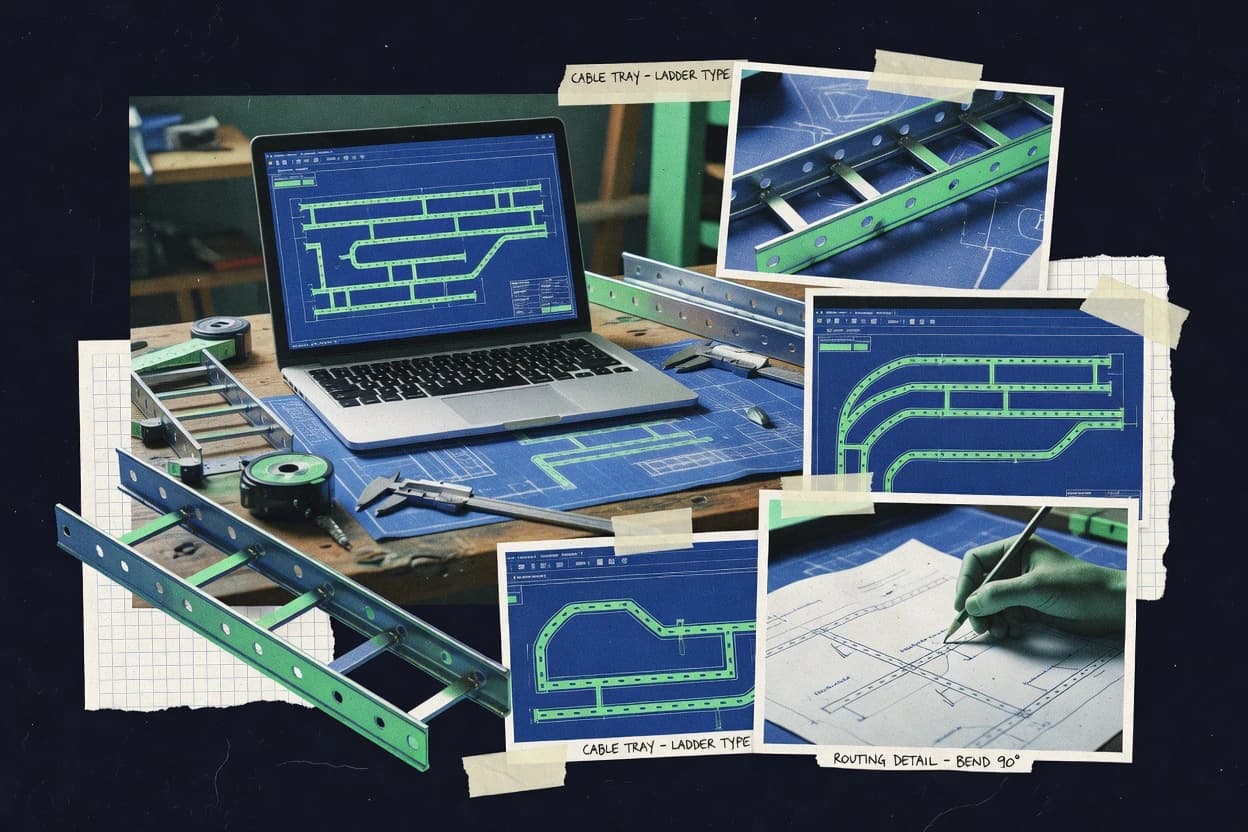
Construction InfrastructureTop 10 Best Cable Tray Design Software of 2026
Compare the top 10 Cable Tray Design Software tools for drafting, modeling, and planning. Explore picks and see how Autodesk Inventor stacks up.

How we ranked these tools
Core product claims cross-referenced against official documentation, changelogs, and independent technical reviews.
Analyzed video reviews and hundreds of written evaluations to capture real-world user experiences with each tool.
AI persona simulations modeled how different user types would experience each tool across common use cases and workflows.
Final rankings reviewed and approved by our editorial team with authority to override AI-generated scores based on domain expertise.
Score: Features 40% · Ease 30% · Value 30%
Gitnux may earn a commission through links on this page — this does not influence rankings. Editorial policy
Editor’s top 3 picks
Three quick recommendations before you dive into the full comparison below — each one leads on a different dimension.
Autodesk Inventor
Parametric assembly modeling with iProperties and drawing views for cable tray runs
Built for engineering teams needing parametric cable tray geometry within broader CAD workflows.
Autodesk Revit
Editor pickBIM-driven parametric families for cable trays and accessories with automatic drawing updates
Built for bIM-driven MEP teams needing coordinated cable tray documentation from one model.
Navisworks
Editor pickClash Detective for rule-based clash detection across coordinated BIM federations
Built for design teams validating cable tray routing and coordinating clashes in federated BIM models.
Related reading
Comparison Table
This comparison table evaluates cable tray design software that integrates modeling, routing support, and clash checking across common CAD and BIM platforms. It compares Autodesk Inventor, Autodesk Revit, Navisworks, Siemens NX, PTC Creo, and other tools on how they generate tray layouts, manage standards, and support coordination between design and construction workflows.
Autodesk Inventor
3D CAD3D CAD software used to model cable tray geometries, supports, and layouts, and to generate fabrication-ready drawings.
Parametric assembly modeling with iProperties and drawing views for cable tray runs
Autodesk Inventor stands out for combining parametric 3D modeling with a full design workflow for creating custom cable tray runs. It supports structured assembly modeling, 3D sketch-driven routing, and generation of drawings for tray layouts and components.
For cable tray design, the strength comes from geometry control, reuse via parts and subassemblies, and compatibility with downstream engineering deliverables. Limitations show up in the need to build or adapt tray-specific rules and content rather than relying on purpose-built cable tray engineering automation.
- +Parametric parts and assemblies enable precise tray geometry control
- +3D drawings and BOM support turn designs into engineering documentation
- +Deep interoperability supports coordination with other CAD and simulation workflows
- +Reusable subassemblies speed consistent tray run creation
- –Tray-specific engineering automation requires setup work or customization
- –Routing workflows are less specialized than dedicated cable tray tools
- –Modeling complex layouts can become slow without careful constraints
- –Content completeness depends on available libraries and standards
Best for: Engineering teams needing parametric cable tray geometry within broader CAD workflows
More related reading
Autodesk Revit
BIMBIM authoring software used to model and coordinate cable tray runs in building information models with clash detection and documentation workflows.
BIM-driven parametric families for cable trays and accessories with automatic drawing updates
Autodesk Revit stands out for cable tray modeling inside a BIM-first workflow where cable trays act as traceable elements in coordinated building geometry. It supports parametric families and detailed component libraries, enabling consistent tray sizes, fittings, and routing logic across drawings.
Revit also enables coordination with linked discipline models and produces construction-ready documentation from the same source model. For cable tray design, its strength is the structured 3D-to-2D documentation loop rather than standalone tray-specific layout automation.
- +BIM-native cable tray elements stay consistent across plans and sections
- +Parametric families and fittings support standardized tray and accessory definitions
- +Model-to-sheet documentation reduces rework during routing changes
- +Links enable coordination with architectural and MEP models in one environment
- –Cable tray routing tools are less specialized than dedicated tray layout software
- –Family authoring requires strong modeling discipline and standards control
- –Large projects can become slower when models and parameters grow
- –Advanced tray optimization often needs manual design decisions
Best for: BIM-driven MEP teams needing coordinated cable tray documentation from one model
Navisworks
CoordinationConstruction coordination software used to review cable tray model clashes and sequence and validate simulation checks across discipline models.
Clash Detective for rule-based clash detection across coordinated BIM federations
Navisworks stands out for its tight integration with Autodesk 3D design sources and its strength in model review workflows rather than standalone cable tray CAD authoring. It supports clash detection, rule-based model checking, and 4D-style coordination use cases through imported model properties. For cable tray design, it excels at validating routing against mechanical and structural constraints and communicating findings through viewpoints and reporting.
- +Robust clash detection with configurable rules across imported BIM models
- +Detailed model review using viewpoints, issue sets, and markups for coordination
- +Supports rule-based checks using model properties for cable routing validation
- –Limited native cable tray parametric editing compared with dedicated CAD tools
- –Model performance degrades with very large federated datasets and heavy geometry
- –Rule setup and property mapping require BIM standards discipline
Best for: Design teams validating cable tray routing and coordinating clashes in federated BIM models
More related reading
Siemens NX
Parametric CADParametric CAD and engineering platform used to design cable tray components, support brackets, and generate production drawings.
Parametric NX modeling of cable tray routes with fittings in assemblies
Siemens NX stands out for cable tray design that plugs into a full mechanical engineering environment rather than living as a standalone tray calculator. It supports parametric modeling of tray routes, fittings, and structural elements with strong assembly and drawing workflows.
Cable tray projects benefit from NX’s mature geometry handling, interference checks, and downstream manufacturing model reuse. The result is strong traceability from 3D design intent to documentation, especially in complex plant layouts.
- +Parametric tray modeling integrates with NX assemblies and drawings
- +Robust geometry and interference checking for crowded plant layouts
- +Good support for creating repeatable tray routing definitions
- +Reuses mechanical design data for downstream documentation workflows
- –Cable tray workflows can feel heavy without NX experience
- –Setup for standards-driven routing takes more modeling discipline
- –Faster tray layout tasks may require specialized add-on workflows
- –Learning curve is steep for teams focused only on cable trays
Best for: Enterprise mechanical design teams needing CAD-native cable tray automation
PTC Creo
Parametric CADParametric 3D CAD used to create cable tray and accessory models, drive standard part libraries, and output drawings for installation.
Parametric modeling for rule-based tray components within complex assemblies
PTC Creo is a full CAD and parametric modeling environment that supports detailed cable tray design with strong 3D geometry control. It enables rule-driven design via its parametric workflows, which helps maintain consistent tray sizing, routing, and connector relationships across revisions. Creo’s assembly context and modeling tools fit well for building coordination-heavy cable tray systems tied to mechanical and structural components.
- +Robust parametric modeling supports consistent tray geometry across revisions
- +Strong assembly-level coordination for integrating trays with supports and structures
- +Works well for complex routing scenarios with detailed connector and support relationships
- –Cable tray specific workflows require setup and template discipline for consistent results
- –Learning curve is steep for teams focused only on tray routing and layout
- –Design changes can trigger broader model updates in large assembly contexts
Best for: Engineering teams needing parametric cable tray modeling inside a broader CAD workflow
Bentley OpenPlant Modeler
Infrastructure BIMPlant and infrastructure modeling software used to author cable tray routes and equipment layouts in engineering models for downstream review.
Plant-data centric model management for cable tray geometry and engineering properties
Bentley OpenPlant Modeler stands out for generating and managing plant design data in a model-centric workflow tied to piping and plant asset concepts. For cable tray design, it supports 3D modeling, routing workflows, and engineering data structures that keep tray geometry and related properties consistent across views. It also benefits from Bentley interoperability and project data management patterns that fit organizations using other OpenPlant and OpenBuildings components.
- +Model-driven workflows keep cable tray geometry aligned with design intent
- +Strong interoperability with Bentley plant ecosystems and related engineering datasets
- +Consistent property management improves downstream coordination and documentation
- –Cable tray-specific workflows can feel heavy without broader plant context
- –Learning curve is steep for users unfamiliar with Bentley modeling concepts
- –Customization and standards setup can consume significant project time
Best for: Engineering teams delivering plant cable tray layouts with Bentley-centric workflows
More related reading
Bentley MicroStation
Drafting/CAD2D and 3D drafting and modeling platform used to produce cable tray drawings, route plans, and layout documentation for construction.
Parametric, rule-driven modeling that enforces standardized cable tray geometry during layout
Bentley MicroStation stands out for its engineering-grade CAD and BIM-style modeling foundation with strong interoperability across Bentley workflows. It supports route-based cable tray modeling, parametric components, and rulesets that can drive consistent layout geometry.
Built-in drafting and visualization tools help teams produce construction-ready drawings from the same model data. For cable tray design specifically, its strengths show up when layouts must integrate with other plant and BIM disciplines in a shared design environment.
- +Parametric geometry supports consistent cable tray routing and component placement
- +Strong integration with broader Bentley design workflows improves multi-discipline coordination
- +Model-to-drawing output supports construction documentation from a shared source model
- –Cable tray-specific automation depends heavily on configured standards and custom rules
- –Advanced modeling and standards setup can slow teams without prior CAD governance
Best for: Engineering teams standardizing cable tray layouts inside Bentley-centric design environments
AVEVA E3D
3D EngineeringEngineering 3D modeling software used to route cable trays and generate engineering model outputs for installation packages.
Integrated cable tray design inside a discipline-wide 3D model for coordinated routing
AVEVA E3D stands out for its deep integration with plant 3D modeling workflows that support engineering-grade layouts and routed systems. It provides cable tray design capabilities with support for 3D placement, routing logic, and coordination against plant models.
The tool also supports downstream deliverables via data-rich model structures that fit large engineering environments and multi-discipline reviews. Its strength shows best on complex, model-driven projects that need consistency across revisions.
- +Strong plant-model coordination for cable tray routing against engineering context
- +Data-rich model structure supports traceable trays, segments, and route changes
- +Works well in multi-discipline 3D review workflows with consistent geometry
- –Complexity can slow cable tray setup without dedicated workflow templates
- –Effective use depends on disciplined model standards and configuration
- –More suitable for enterprise engineering than lightweight tray layout tasks
Best for: Large engineering teams needing consistent cable tray routing in 3D plant models
More related reading
AVEVA PDMS
Plant designPlant design modeling software used to create cable tray routing and structure layouts for engineering and model-based documentation.
Spec-driven cable tray layout generation within PDMS plant data structures
AVEVA PDMS stands out for its strong foundation in 3D plant design and its tight integration with structured engineering data for layout-driven work. It supports cable tray routing, configuration, and 3D modeling tied to engineering specifications, which helps keep tray layouts consistent across revisions. The workflow is strongest for large, discipline-coordinated projects where model navigation, clash checking support, and data consistency matter more than quick, standalone drafting.
- +Deep 3D plant modeling tied to engineering data for traceable cable tray layouts
- +Strong support for structured routing and repeatable tray configuration in complex models
- +Good interoperability with enterprise plant engineering workflows
- +Scales well for multi-discipline projects requiring consistent model updates
- +Supports model-based coordination activities like spatial review and issue localization
- –Cable tray design workflows can feel heavy for small, standalone drawing tasks
- –Mastering the modeling and data-structure concepts takes substantial training
- –UI responsiveness can lag on large plant models with dense geometry
- –Customization of rules and outputs may require specialist configuration work
- –Standalone productivity for ad hoc tray reroutes can be slower than lightweight tools
Best for: Large plant teams needing specification-driven 3D cable tray layouts in PDMS workflows
Trimble Tekla Structures
Structural coordinationStructural modeling software used to coordinate support steel frames and cable tray mounting interfaces with construction drawings.
Model-based parametric detailing with assembly-controlled drawings and schedules
Trimble Tekla Structures stands out for cable tray modeling inside a full structural detailing workflow tied to real geometry and assemblies. It supports creating and positioning tray runs, supports, and related steel components with parametric templates and BIM coordination.
The software excels at producing construction-ready documentation and automated rebar and steel-style detailing outputs for clashes between cable systems and structural elements. It is less focused on lightweight, cable-tray-specific design automation than dedicated MEP tray tools.
- +Parametric detailing workflow for cable tray geometry and associated supports
- +Strong clash detection and coordination with structural models and assemblies
- +Automated drawing generation for tray routes and fabrication-grade member views
- –Primarily structural modeling experience makes tray design workflows heavier
- –Tray-specific automation is weaker than dedicated cable tray design software
- –Setup of templates and parameters can require significant admin effort
Best for: Projects needing coordinated cable tray detailing within structural BIM models
How to Choose the Right Cable Tray Design Software
This buyer’s guide explains how to evaluate cable tray design software options that range from CAD modeling platforms like Autodesk Inventor and PTC Creo to BIM and plant workflows like Autodesk Revit, Bentley OpenPlant Modeler, AVEVA E3D, and AVEVA PDMS. It also covers validation and coordination tools like Navisworks and documentation and structural coordination workflows like Bentley MicroStation and Trimble Tekla Structures. The guide ties buying decisions to concrete capabilities such as parametric assemblies, clash detection, and model-driven documentation updates.
What Is Cable Tray Design Software?
Cable tray design software creates and manages the 3D geometry of tray routes, fittings, and supports so drawings, schedules, and coordination artifacts stay consistent as layouts change. It solves recurring problems like routing complexity in crowded environments, document rework after routing changes, and coordination conflicts across architectural, structural, and MEP models. Autodesk Inventor represents a CAD-first example where parametric assemblies generate tray geometry and engineering drawings. Autodesk Revit represents a BIM-first example where cable tray elements and accessories update automatically across plans and sections inside a coordinated building model.
Key Features to Look For
Cable tray projects fail most often when teams pick tools that cannot preserve standardized geometry and traceability from design intent to documentation and coordination.
Parametric assembly modeling for tray routes, fittings, and drawings
Autodesk Inventor excels at parametric assembly modeling for cable tray runs and uses drawing views plus iProperties to tie geometry to documentation. Siemens NX and PTC Creo also support parametric modeling in assembly contexts, which improves traceability when supports and structural interfaces must align with the tray system.
BIM-native cable tray elements that update documentation from one model
Autodesk Revit provides BIM-driven parametric families for trays and accessories and automatically updates drawings when the model changes. This model-to-sheet documentation loop reduces plan and section rework compared with workflows that treat drawings as the primary output.
Rule-based clash detection and model checking for coordinated routing
Navisworks delivers robust clash detection using configurable rules across imported BIM federations through Clash Detective. It also supports viewpoints, issue sets, and markups to communicate routing and constraint findings across disciplines without requiring native cable tray editing.
Plant-model data structures that keep trays consistent across revisions
Bentley OpenPlant Modeler provides plant-data centric model management so cable tray geometry stays aligned with design intent and engineering properties across views. AVEVA E3D and AVEVA PDMS emphasize discipline-wide 3D plant modeling and spec-driven layouts with data-rich model structures for traceable route changes.
Standardized, rule-driven layout geometry enforcement
Bentley MicroStation supports parametric, rule-driven modeling that enforces standardized cable tray geometry during layout. This is a strong fit when teams must keep tray routes, components, and drafting outputs consistent across multi-discipline design environments.
Structural BIM detailing and construction documentation for tray supports
Trimble Tekla Structures combines model-based parametric detailing with clash-aware coordination against structural models and supports automated drawing generation for tray routes and fabrication-grade member views. This capability matters when cable trays must integrate tightly with steel frames and support detailing rather than living as a standalone MEP-only model.
How to Choose the Right Cable Tray Design Software
A reliable selection starts with matching the tool’s modeling and coordination core to the delivery workflow used by the project team.
Pick the workflow core: CAD parametric modeling, BIM authoring, or plant modeling
Choose Autodesk Inventor or Siemens NX when tray routes must be built as parametric assemblies with geometry control and engineering drawing views. Choose Autodesk Revit when the project requires BIM-native cable tray elements and automatic plan and section updates from a single coordinated model. Choose Bentley OpenPlant Modeler, AVEVA E3D, or AVEVA PDMS when the project treats cable tray design as part of a plant-data workflow that must preserve engineering properties across revisions.
Validate routing constraints through a dedicated coordination or clash workflow
Use Navisworks when the project combines federated BIM sources and needs configurable rule-based clash detection using Clash Detective. Use Siemens NX or Autodesk Inventor when interference checking happens inside the same CAD model as the tray assemblies, especially for crowded plant layouts. Expect separate setup work when mapping routing validation rules to model properties is required in federated environments.
Demand documentation and properties that stay synchronized as routing changes
Select Autodesk Revit for automatic drawing updates driven by BIM-native parametric families for cable trays and accessories. Select Autodesk Inventor for drawing views tied to parametric assemblies and iProperties so BOM-style information stays consistent with geometry. Select AVEVA E3D or AVEVA PDMS when data-rich model structures and traceable trays and segments are required for installation package outputs.
Confirm standards control for tray families and rulesets before large production work
Expect workflow setup and standards governance work in Autodesk Inventor, PTC Creo, Siemens NX, Bentley MicroStation, and Bentley OpenPlant Modeler because cable tray-specific automation and rulesets rely on configured rules and content. Choose Autodesk Revit when parametric families and fittings support standardized tray and accessory definitions with model-wide consistency. Treat setup discipline as a requirement because large models and parameter sets can reduce responsiveness across Revit-like BIM and plant ecosystems.
Align structural detailing needs with the right authoring scope
Choose Trimble Tekla Structures when cable trays must integrate with structural frames and require assembly-controlled drawings and schedules for support steel interfaces. Choose CAD or plant modeling tools like Siemens NX, Bentley OpenPlant Modeler, or AVEVA E3D when the primary need is tray routing with plant or mechanical engineering context rather than steel detailing automation. Use Navisworks when clashes must be communicated through viewpoints and issue sets rather than resolved inside a structural detailing authoring environment.
Who Needs Cable Tray Design Software?
Cable tray design software is best for teams that must produce route geometry and documentation that stay consistent across discipline coordination and revision cycles.
BIM-driven MEP teams that must coordinate cable tray drawings from one model
Autodesk Revit fits because BIM-native cable tray elements and parametric families update automatically across plans and sections. The ability to link architectural and MEP models supports clash coordination while keeping tray and accessory definitions standardized.
Engineering CAD teams that need parametric tray geometry inside a broader CAD ecosystem
Autodesk Inventor and PTC Creo fit because both deliver parametric 3D modeling and assembly context for cable tray routes, fittings, and supports. Siemens NX also fits for enterprise mechanical engineering environments that require interference checks and downstream documentation traceability.
Plant engineering teams delivering discipline-wide 3D cable tray routing with traceable engineering properties
Bentley OpenPlant Modeler fits because it manages cable tray geometry and engineering properties in a plant-data-centric workflow. AVEVA E3D and AVEVA PDMS fit because both provide integrated cable tray design inside plant 3D models with data-rich structures that support revision-consistent outputs.
Projects that require coordinated structural detailing for cable tray mounting interfaces
Trimble Tekla Structures fits when cable tray supports and interfaces must be coordinated with real structural geometry and assembly templates. It also fits when automated drawing generation and clash coordination against structural models are required for construction-ready documentation.
Common Mistakes to Avoid
Common selection failures happen when teams ignore the tool’s automation scope and the standards setup burden required for repeatable cable tray geometry.
Treating a general CAD tool as cable tray automation without planning for standards setup
Autodesk Inventor, PTC Creo, Siemens NX, and Bentley MicroStation can produce accurate tray geometry but cable tray-specific engineering automation depends on configured rules and standards content. Teams should plan for rules and templates work so tray routing definitions and component libraries remain consistent across project revisions.
Skipping a dedicated coordination pass for federated model clash validation
Navisworks is designed for rule-based clash detection using Clash Detective across coordinated BIM federations and it can produce issue sets with viewpoints and markups. Relying only on tray modeling in Autodesk Revit, Siemens NX, or AVEVA tools can miss coordination constraints that appear only after model federation and property mapping.
Overlooking performance and usability penalties in large, parameter-heavy models
Autodesk Revit can slow down on large projects when model complexity and parameter sets grow. Navisworks and AVEVA PDMS-like plant workflows can also degrade responsiveness with very large federated datasets or dense geometry, so teams need a workflow that manages dataset scope.
Choosing a structural detailing platform as the primary cable tray layout engine
Trimble Tekla Structures excels at coordinated detailing with assembly-controlled drawings and schedules, but tray-specific automation is weaker than dedicated cable tray design tools. Projects that need fast ad hoc tray reroutes should combine structural coordination output with CAD or BIM-native tray routing where automation is stronger.
How We Selected and Ranked These Tools
We evaluated every tool on three sub-dimensions. Features carry weight 0.4, ease of use carries weight 0.3, and value carries weight 0.3. The overall rating is computed as overall = 0.40 × features + 0.30 × ease of use + 0.30 × value. Autodesk Inventor separated from lower-ranked options mainly because its feature set combined parametric assembly modeling for precise tray geometry with drawing views and iProperties tied to cable tray runs, which improved both documentation outcomes and day-to-day productivity for engineering deliverables.
Frequently Asked Questions About Cable Tray Design Software
Which tool is best for parametric, drawing-ready cable tray routing without switching away from a broader CAD workflow?
Which option fits a BIM-first process where cable trays must be traceable, coordinated, and documented from one model?
When clash detection and routing validation across federated models matter more than creating tray geometry from scratch, which software is a better match?
Which CAD platform is best suited for cable tray design inside an enterprise mechanical engineering environment with interference checking and assembly traceability?
Which tool is designed for cable tray layouts driven by plant asset data structures instead of only geometry?
Which solution is most appropriate when cable tray routing needs deep integration with plant 3D models and multi-discipline reviews?
How do structural detailing workflows change the choice of cable tray design software?
What is the most effective workflow for standardizing cable tray geometry and rules across a team using a single shared modeling environment?
Which tool should be used when the main priority is end-to-end model coordination, reporting, and review visibility for routed systems?
Conclusion
After evaluating 10 construction infrastructure, Autodesk Inventor stands out as our overall top pick — it scored highest across our combined criteria of features, ease of use, and value, which is why it sits at #1 in the rankings above.
Use the comparison table and detailed reviews above to validate the fit against your own requirements before committing to a tool.
Tools reviewed
Primary sources checked during evaluation.
Referenced in the comparison table and product reviews above.
Keep exploring
Comparing two specific tools?
Software Alternatives
See head-to-head software comparisons with feature breakdowns, pricing, and our recommendation for each use case.
Explore software alternatives→In this category
Construction Infrastructure alternatives
See side-by-side comparisons of construction infrastructure tools and pick the right one for your stack.
Compare construction infrastructure tools→FOR SOFTWARE VENDORS
Not on this list? Let’s fix that.
Our best-of pages are how many teams discover and compare tools in this space. If you think your product belongs in this lineup, we’d like to hear from you—we’ll walk you through fit and what an editorial entry looks like.
Apply for a ListingWHAT THIS INCLUDES
Where buyers compare
Readers come to these pages to shortlist software—your product shows up in that moment, not in a random sidebar.
Editorial write-up
We describe your product in our own words and check the facts before anything goes live.
On-page brand presence
You appear in the roundup the same way as other tools we cover: name, positioning, and a clear next step for readers who want to learn more.
Kept up to date
We refresh lists on a regular rhythm so the category page stays useful as products and pricing change.