GITNUXSOFTWARE ADVICE
Manufacturing EngineeringTop 10 Best Breadboard Layout Software of 2026
Top 10 Breadboard Layout Software for 2026. Compare top picks like Fusion 360, Altium Designer, and KiCad, then choose fast.

How we ranked these tools
Core product claims cross-referenced against official documentation, changelogs, and independent technical reviews.
Analyzed video reviews and hundreds of written evaluations to capture real-world user experiences with each tool.
AI persona simulations modeled how different user types would experience each tool across common use cases and workflows.
Final rankings reviewed and approved by our editorial team with authority to override AI-generated scores based on domain expertise.
Score: Features 40% · Ease 30% · Value 30%
Gitnux may earn a commission through links on this page — this does not influence rankings. Editorial policy
Editor’s top 3 picks
Three quick recommendations before you dive into the full comparison below — each one leads on a different dimension.
Autodesk Fusion 360
Associative 3D CAD linking for component placement, clearances, and enclosure interference checking
Built for teams needing PCB-to-mechanics integration and manufacturing-ready outputs.
Altium Designer
Editor pickConnectivity-driven synchronization between schematic nets and physical placement objects
Built for engineers prototyping connectivity in Altium, then routing to production PCBs.
KiCad
Editor pickInteractive netlist and footprint linking from schematic to physical layout
Built for designers transitioning from breadboard wiring to PCB layout in one ecosystem.
Related reading
Comparison Table
This comparison table reviews breadboard layout software used to plan wiring, place components, and validate connectivity before prototyping. It contrasts tools such as Autodesk Fusion 360, Altium Designer, KiCad, OrCAD / Allegro, and PADS across key workflow areas like schematic-to-layout support, library management, wiring and routing behavior, and export options.
Autodesk Fusion 360
CAD+electronicsFusion 360 supports electronics design workflows with schematic capture and PCB layout plus 3D modeling for enclosure fit and mechanical-electrical integration.
Associative 3D CAD linking for component placement, clearances, and enclosure interference checking
Autodesk Fusion 360 stands out for merging PCB design tooling with full 3D CAD and CAM capabilities in a single workflow. Its electronics-centric environment supports board layout tasks plus tight mechanical integration so enclosure fit and component clearances can be checked early.
The software also enables parametric modeling and simulation-driven iterations that reduce layout rework when mechanical constraints change. Collaboration and file-based data management support design review cycles with downstream manufacturing documentation.
- +Strong mechanical-to-PCB integration for enclosure fit and clearance checks
- +Parametric modeling supports repeatable design updates across assemblies
- +Generates manufacturing-oriented outputs aligned with CAD and CAM workflows
- +Integrated history and parameters help track design intent during revisions
- +Workflow supports iterative refinement between board layout and 3D models
- –Electronics-specific tasks feel less streamlined than dedicated PCB tools
- –Learning curve rises due to deep CAD, CAM, and modeling concepts
- –Breadboard-level prototyping benefits are limited compared with breadboard-first apps
Best for: Teams needing PCB-to-mechanics integration and manufacturing-ready outputs
More related reading
Altium Designer
pro PCB designAltium Designer provides schematic capture and PCB layout with advanced routing, constraint-driven design, and manufacturing-ready export packages.
Connectivity-driven synchronization between schematic nets and physical placement objects
Altium Designer stands out with a unified schematic-to-PCB workflow built around a single, deeply integrated design data model. For breadboard layout work, it supports component placement, net connectivity, and rules-driven design synchronization that later carries into PCB design.
Its strength shows when using breadboard style prototyping as a stepping stone to manufacturable PCB outputs. The same project structure helps teams maintain connectivity integrity across stages.
- +Tight schematic and layout data linkage reduces net mismatch during prototyping
- +Rules-driven design checks catch connectivity and constraint issues early
- +Breadboard-style placement can transition cleanly into PCB design workflows
- –Breadboard-centric workflows can feel heavier than simple wiring layout tools
- –Learning curve is steep due to comprehensive PCB and design rule systems
- –Virtual breadboard ergonomics are less optimized than dedicated breadboard apps
Best for: Engineers prototyping connectivity in Altium, then routing to production PCBs
KiCad
open-source EDAKiCad offers schematic capture and PCB layout with a component library ecosystem and export tools for manufacturing workflows.
Interactive netlist and footprint linking from schematic to physical layout
KiCad stands out with one integrated open-source workflow that combines schematic design and PCB layout tooling, including strong footprint and net management for physical builds. Breadboard layouts are supported through external workflows, custom scripts, and reusable symbols or footprints, so users can still plan wiring and component placement before committing to a board. The core strengths align with creating consistent component references, keeping pin-to-net intent traceable, and exporting manufacturable definitions when moving from breadboard thinking to PCB execution.
- +Tight schematic-to-footprint consistency helps map breadboard wiring intent
- +Powerful library and symbol handling supports reusable component definitions
- +Vector-accurate exports enable consistent documentation and later PCB transition
- –Breadboard-specific constraints like rails and rows need manual modeling
- –Pin-to-pin breadboard automation is weaker than dedicated breadboard tools
- –Learning curve is higher due to PCB-centric interface and concepts
Best for: Designers transitioning from breadboard wiring to PCB layout in one ecosystem
More related reading
OrCAD / Allegro
enterprise PCBAllegro PCB Design System enables schematic-driven PCB layout with constraint handling and manufacturing data generation.
Allegro interactive router with connectivity-driven constraint management
OrCAD and Allegro are distinct because they combine schematic capture with advanced PCB layout workflows used in professional electronics design flows. For breadboard layout tasks, they can still support pin-level connectivity planning through netlists, hierarchical parts, and electrical rule checks exported from schematic to layout.
The workflow is strong for translating known connectivity and constraints into a physical layout representation, but it is not optimized for fast breadboard-style placement the way dedicated breadboard tools are. Expect reliance on PCB-centric objects like footprints, layers, and routing instead of breadboard-specific grids and jumper modeling.
- +Netlist-driven placement from schematic to layout reduces wiring mistakes
- +Constraint and connectivity checking helps maintain correct pin mapping
- +Footprints and device libraries support detailed representation of components
- +Hierarchical design supports large projects with reusable blocks
- –Breadboard-specific grid placement and jumper behaviors are not core
- –Tool complexity slows layout work for quick breadboard prototypes
- –PCB-centric layers and routing models add friction to non-PCB layouts
- –Large library management overhead can distract from early experimentation
Best for: Teams migrating breadboard concepts into PCB-ready connectivity and constraints
PADS
enterprise PCBPADS by Siemens supports PCB design and layout workflows with schematic capture integration and fabrication outputs.
Constraint-driven design rule checking during placement and routing
PADS by Mentor is a PCB design suite with strong breadboard-style workflow support through its component placement and wiring visualization. It supports library-managed parts and rule-driven connectivity checks, which helps keep physical prototyping layouts aligned with schematic intent. Layout constraints and design checking features support repeatable placement and routing outcomes instead of purely manual drawing.
- +Tight schematic-to-layout connectivity reduces wiring mismatches
- +Rule-driven design checks catch shorts and connectivity issues early
- +Component libraries support consistent placement across iterations
- –Breadboard-style placement feels less purpose-built than dedicated breadboard tools
- –Learning curve is steep for teams focused on fast prototyping
- –Layout-first workflow can slow quick one-off wiring diagrams
Best for: Teams migrating from breadboards to routed PCB layouts
EasyEDA
cloud EDAEasyEDA is an electronics CAD tool that supports schematic entry and PCB layout with cloud collaboration and export for fabrication.
Schematic-to-breadboard synchronization with automatic net connections
EasyEDA stands out for combining a breadboard layout workflow with a full circuit design editor and schematic-to-layout consistency. The board canvas supports placement of common components and wiring that can be visualized as a breadboard-style build plan.
Library-driven parts and net connections help maintain electrical coherence between the schematic view and the breadboard view. The tool remains more focused on electronics assembly visualization than on producing production-grade manufacturing documentation from the breadboard alone.
- +Schematic and breadboard views keep net connectivity consistent during edits
- +Extensive component library supports rapid placement and wiring on a breadboard
- +Clear visual wiring makes build plans easy to follow
- –Breadboard-specific controls feel less specialized than dedicated breadboard tools
- –Large layouts can become sluggish during frequent placement and rerouting
- –Exporting breadboard-focused documentation is limited compared to full CAD flows
Best for: Students and makers creating visual breadboard wiring plans with circuit consistency
More related reading
tinkercad Circuits
breadboard simulationTinkercad Circuits provides a breadboard-style electronics simulator for placing components and validating circuits before hardware build.
Live circuit simulation tied directly to breadboard wiring
Tinkercad Circuits stands out with a browser-based breadboard and circuit simulator that supports drag-and-drop wiring. It provides a visual parts palette, interactive breadboard placement, and instant feedback through built-in simulation.
The workflow is tightly integrated with basic coding blocks and ready-to-test circuits, which fits quick prototyping and classroom use. Breadboard layouts can be organized and iterated quickly, but advanced electronics workflows need limits beyond simple educational circuits.
- +Browser-only breadboard layout with drag-and-drop parts and wiring
- +Real-time simulation feedback for LEDs, switches, and common components
- +Clean beginner-friendly interface with guided component placement
- +Works well for quick experiments and classroom-style circuit iterations
- –Limited support for advanced components and professional-level layouts
- –No native PCB layout export workflow for production-ready fabrication
- –Breadboard-focused controls can feel restrictive for complex wiring
Best for: Teaching, rapid prototyping, and simple breadboard circuit simulation
Fritzing
documentation-firstFritzing enables breadboard visualization, schematic-like documentation, and PCB layouts for prototyping and maker-oriented manufacturing prep.
Single-project multi-view editing across Breadboard, Schematic, and PCB
Fritzing stands out for turning breadboard and schematic work into a single visual model that can be rearranged without leaving the editor. It supports creating breadboard layouts with draggable components, wiring across rows and rails, and generating corresponding schematic and PCB views from the same design data.
The workflow also includes basic part management so custom or missing components can be approximated using available library parts. The tool is strong for learning and quick prototypes but weaker for large, tightly managed boards due to limited project-scale organization.
- +Breadboard view stays synchronized with schematic and parts placement
- +Drag-and-drop wiring makes initial circuits fast to assemble visually
- +Component library supports common electronics parts for quick prototyping
- +Export paths support further editing in other EDA or documentation flows
- –Breadboard accuracy depends on fitting parts to specific footprints
- –Large projects become harder to manage and visually scan
- –Advanced constraints and engineering checks are limited versus pro ECAD tools
- –Custom part creation and library upkeep require extra manual work
Best for: Learning and small prototype breadboard layouts needing visual documentation
More related reading
Autodesk EAGLE
classic PCB designAutodesk EAGLE offers schematic and PCB layout with libraries and production output suited for prototyping and manufacturing.
Netlist synchronization between schematic and board layout for consistent connectivity
Autodesk EAGLE stands out with a tightly integrated schematic-to-PCB workflow built around its long-running EAGLE library ecosystem. It supports breadboard-style wiring and net planning through the same netlist-driven project structure used for PCB layout.
Component placement, wiring, and ERC style checks help reduce connectivity mistakes before routing. For breadboard layout specifically, it offers practical visualization and verification when paired with accurate packages from existing libraries.
- +Netlist-driven wiring reduces mismatched connections across schematic and layout
- +Large component library selection speeds breadboard planning for common parts
- +Design rule style checks catch many electrical issues early
- +Fast component placement and interactive routing for board-ready layouts
- –Breadboard-specific ergonomics feel less polished than dedicated breadboard tools
- –Library and footprint accuracy requires active management for reliable results
- –Workflow complexity rises for larger projects with many sheets and nets
Best for: Engineers validating wiring before PCB routing with strong library support
Proteus
simulation EDAProteus provides schematic capture plus virtual instrument and electronics simulation workflows with breadboard-style component placement.
Schematic-linked breadboard placement that keeps nets consistent across design
Proteus centers on an electronics design workflow that pairs schematic capture with breadboard-style layout and simulation. The breadboard environment supports placing components onto realistic board views and routing connections to match the schematic intent.
Library depth and linkage between the schematic netlist and the physical layout are the key strengths. The simulator-driven workflow helps validate wiring decisions earlier than in layout-only tools.
- +Tight schematic-to-breadboard net connectivity reduces wiring rework
- +Component libraries include many real-world ICs and passive parts
- +Simulation feedback highlights wiring faults before physical build
- +Visual breadboard placement supports clear documentation of prototypes
- –Breadboard placement workflow can feel slower than layout-first tools
- –Advanced routing and cleanup require deliberate manual tweaking
- –Large prototype projects can become heavy to navigate and edit
Best for: Engineers validating breadboard prototypes with simulation-driven wiring checks
How to Choose the Right Breadboard Layout Software
This buyer's guide explains how to select breadboard layout software by comparing breadboard-first tools and ECAD suites that support breadboard-style workflows. It covers Autodesk Fusion 360, Altium Designer, KiCad, OrCAD / Allegro, PADS, EasyEDA, tinkercad Circuits, Fritzing, Autodesk EAGLE, and Proteus.
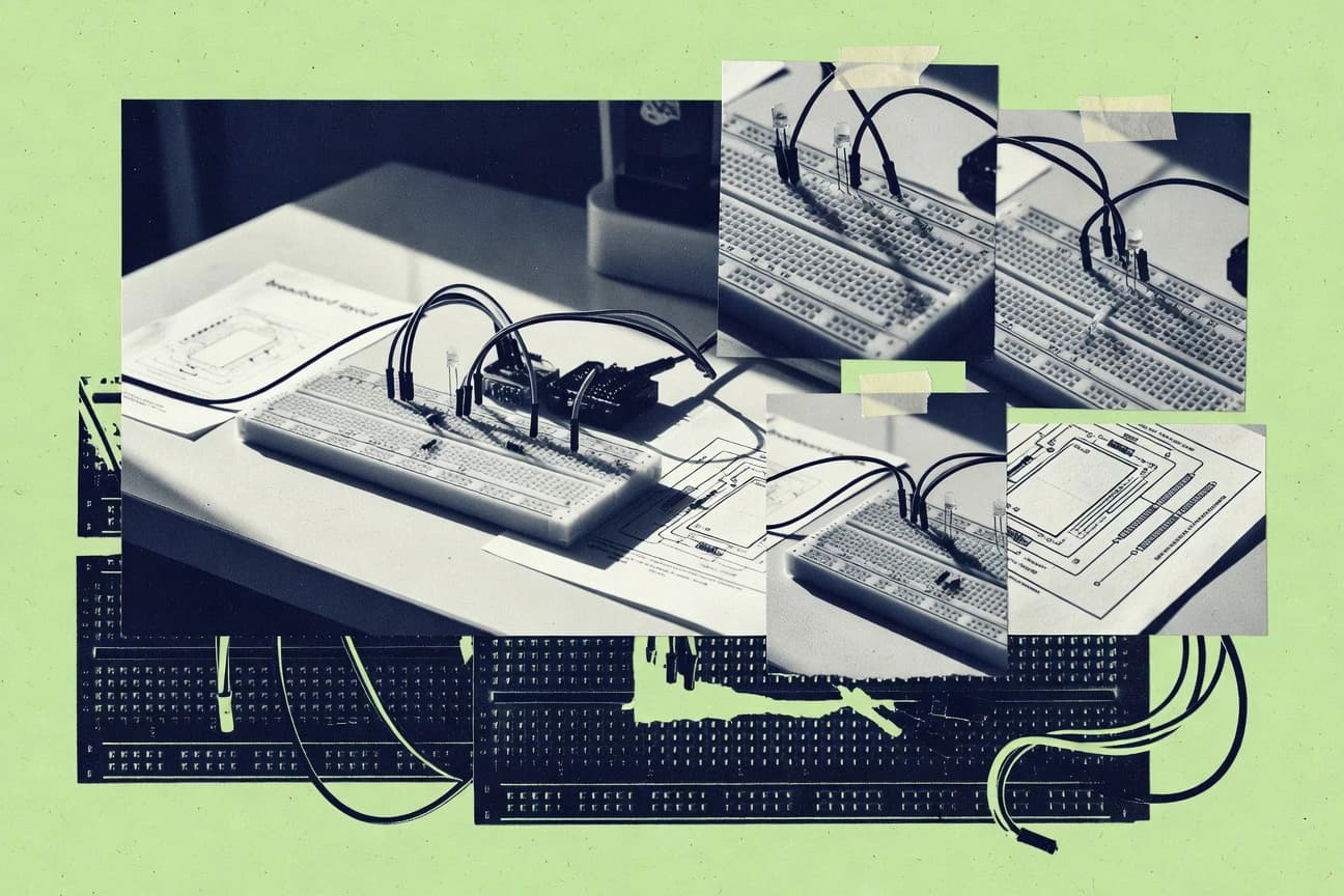
What Is Breadboard Layout Software?
Breadboard layout software is an electronic design tool that helps place components onto a breadboard grid or breadboard-style canvas and wire them to match an intended circuit. Many tools also synchronize breadboard wiring with a schematic netlist to reduce connection mistakes during iteration. Some products add simulation so wiring faults are caught before a physical build, including tinkercad Circuits and Proteus. Other ECAD suites such as Altium Designer and Autodesk EAGLE support breadboard-style visualization but are primarily optimized for PCB-ready workflows.
Key Features to Look For
The right feature set determines whether breadboard work stays consistent, fast, and transferable to simulation or PCB execution.
Schematic-to-breadboard or schematic-to-layout connectivity synchronization
Connectivity synchronization prevents net mismatches when changes happen after initial placement. EasyEDA focuses on schematic-to-breadboard synchronization with automatic net connections, while Proteus keeps schematic-linked breadboard placement so nets stay consistent across the design. Altium Designer also synchronizes schematic nets with physical placement objects to reduce wiring mistakes during prototyping.
Live circuit simulation tied directly to breadboard wiring
Simulation attached to breadboard wiring catches wiring faults while the prototype is still being arranged. tinkercad Circuits provides browser-based simulation feedback tied directly to breadboard placement, including validation for components like LEDs and switches. Proteus pairs schematic capture with breadboard-style layout and simulation so wiring decisions are validated earlier than in layout-only tools.
Multi-view editing across Breadboard, Schematic, and PCB
Multi-view editing keeps one design object model across representations so the same placement and wiring can be reused. Fritzing offers a single-project workflow that supports Breadboard, Schematic, and PCB views from the same design data. This structure reduces the friction of rearranging the breadboard while maintaining consistent documentation.
Rules-driven constraint checking during placement and routing
Constraint and rule checks reduce shorts and pin mapping mistakes when wiring expands beyond a small prototype. PADS provides constraint-driven design rule checking during placement and routing, while OrCAD / Allegro supports constraint and connectivity checking exported from schematic to layout. Altium Designer also uses rules-driven design checks to catch connectivity and constraint issues early.
Associative connectivity and mechanical fit verification through 3D
When enclosure clearance matters, associative linking between the electrical placement and mechanical model prevents late rework. Autodesk Fusion 360 stands out with associative 3D CAD linking for component placement, clearances, and enclosure interference checking. This approach helps teams refine board layout while accounting for mechanical constraints.
Breadboard-first ergonomics for drag-and-drop prototyping
Breadboard-specific controls speed early wiring and placement by matching how breadboards are actually used. tinkercad Circuits provides browser-only drag-and-drop breadboard placement with a beginner-friendly interface. Fritzing also emphasizes draggable breadboard components and drag-and-drop wiring to assemble circuits quickly for learning and small prototypes.
How to Choose the Right Breadboard Layout Software
A practical decision starts with whether the workflow must stay breadboard-first, must carry into PCB execution, or must include simulation and mechanical clearance checks.
Choose the primary workflow type: breadboard-first, ECAD-first, or simulation-first
For breadboard-first prototyping with fast drag-and-drop wiring, start with tinkercad Circuits and Fritzing because both provide breadboard-specific placement and wiring experiences. For simulation-first verification tied to the breadboard, choose tinkercad Circuits for instant feedback or Proteus for schematic-linked breadboard simulation. For ECAD-first workflows that still support breadboard-style planning as part of a larger electronics flow, choose Altium Designer or Autodesk EAGLE.
Prioritize connectivity synchronization to avoid net mismatch during edits
If net consistency across representations matters, pick tools that synchronize schematic nets with breadboard or placement objects. EasyEDA synchronizes schematic and breadboard views with automatic net connections. Altium Designer synchronizes connectivity between schematic nets and physical placement objects, while Proteus keeps schematic-linked breadboard placement so nets remain consistent during iteration.
Verify whether constraint checking must happen during early placement
For projects where shorts, pin mapping errors, and rule violations must be caught as early as placement, prioritize constraint-driven design checks. PADS provides constraint-driven design rule checking during placement and routing. OrCAD / Allegro supports constraint and connectivity checking through an Allegro interactive router that is driven by connectivity constraints, and Altium Designer uses rules-driven design checks for connectivity and constraint issues.
Decide how transferable the breadboard work must be to PCB execution
If breadboard work must transition cleanly into manufacturable PCB design, use tools that maintain a single design data model across stages. Altium Designer uses a unified schematic-to-PCB workflow with connectivity-driven synchronization that supports stepping from breadboard-style placement to production routing. KiCad supports schematic-to-footprint consistency and interactive netlist and footprint linking, while Fritzing provides synchronized Breadboard, Schematic, and PCB views within the same project.
Include mechanical fit checks only when the enclosure is a constraint
When component clearances and enclosure interference drive layout decisions, Autodesk Fusion 360 is built for associative mechanical-electrical integration. Its associative 3D CAD linking checks component clearances and interference so board placement changes can be evaluated against mechanical constraints early. This mechanical-to-PCB integration is not a core strength in breadboard-first tools like Fritzing or tinkercad Circuits.
Who Needs Breadboard Layout Software?
Breadboard layout software fits a spectrum from classroom simulation to professional prototype planning and PCB transition workflows.
Teams needing enclosure fit validation with electrical placement
Autodesk Fusion 360 fits teams that must validate enclosure fit and clearances by linking component placement into associative 3D CAD so interference checking can happen during layout iteration. Fusion 360 also combines PCB design tooling with full 3D CAD and CAM so mechanical-electrical integration stays in one workflow.
Engineers prototyping connectivity before routing production PCBs
Altium Designer fits engineers who want schematic-to-PCB continuity and connectivity-driven synchronization between schematic nets and physical placement objects. Altium Designer also uses rules-driven design checks to catch connectivity and constraint issues early, which supports a smooth path from breadboard-style prototyping to manufacturable PCB routing.
Designers transitioning from breadboard wiring into PCB layout within one ecosystem
KiCad fits designers who want consistent component references and traceable pin-to-net intent through interactive netlist and footprint linking. KiCad keeps schematic-to-footprint consistency strong, which supports moving breadboard wiring decisions into PCB execution without losing mapping intent.
Students, makers, and educators building fast breadboard circuits with verification
tinkercad Circuits fits classroom use and rapid breadboard prototyping because it provides browser-only drag-and-drop placement with live simulation tied directly to the breadboard wiring. EasyEDA also fits students and makers who want visual wiring plans with schematic-to-breadboard synchronization and automatic net connections for electrical coherence.
Common Mistakes to Avoid
Many project failures come from choosing a tool that cannot keep connectivity consistent, lacks verification, or slows the specific workflow needed for prototypes.
Choosing a tool without connectivity synchronization across representations
Net mismatches are common when schematic intent is not synchronized with breadboard wiring or placement objects. EasyEDA prevents many of these errors with schematic-to-breadboard synchronization and automatic net connections, and Proteus prevents rework with schematic-linked breadboard placement that keeps nets consistent across design.
Relying on a breadboard layout tool for simulation when verification is required
Breadboard-only wiring without simulation increases the chance of wiring faults being discovered late. tinkercad Circuits ties live circuit simulation directly to breadboard wiring for rapid validation, and Proteus adds simulation-driven workflow so wiring decisions are validated earlier than with layout-only prototyping.
Forgetting that pro ECAD tools feel heavier for breadboard-style placement
PCB-centric tools can slow quick one-off wiring diagrams because they rely on footprints, layers, and routing models instead of breadboard grids and jumper behaviors. OrCAD / Allegro and PADS both support connectivity planning through netlists and rule checking, but their breadboard-specific grid placement is not a core strength compared with breadboard-first tools like tinkercad Circuits and Fritzing.
Expecting accurate component-to-breadboard matching without footprint and part discipline
Breadboard accuracy can degrade when components do not map cleanly to the modeled footprint used in the tool. Fritzing notes that breadboard accuracy depends on fitting parts to specific footprints, and KiCad similarly requires manual modeling for breadboard-specific constraints like rails and rows.
How We Selected and Ranked These Tools
We evaluated every tool on three sub-dimensions with weights of features at 0.4, ease of use at 0.3, and value at 0.3. The overall score equals 0.40 × features plus 0.30 × ease of use plus 0.30 × value. Autodesk Fusion 360 separated itself by delivering standout capabilities that combine associatively linked component placement with 3D mechanical fit and clearances, which strongly supports its features dimension. That combination helped Fusion 360 remain highly usable for teams needing mechanical-electrical integration instead of limiting work to breadboard wiring alone.
Frequently Asked Questions About Breadboard Layout Software
Which tool best keeps breadboard wiring consistent with a real PCB layout?
What software is strongest when breadboard planning must connect to mechanical constraints?
Which option supports breadboard-style visualization but still helps validate electrical behavior early?
Which tool is most suitable for teaching and rapid classroom prototyping?
How should users choose between Fritzing and dedicated PCB suites for documentation?
Which software handles breadboard-to-PCB work in a unified electronics workflow without proprietary lock-in?
Which tool is best for exporting rule-checked connectivity after a breadboard-style plan?
What is the most practical workflow for turning breadboard wiring into a circuit assembly plan?
Which software is better suited for large projects with strict organization requirements?
Conclusion
After evaluating 10 manufacturing engineering, Autodesk Fusion 360 stands out as our overall top pick — it scored highest across our combined criteria of features, ease of use, and value, which is why it sits at #1 in the rankings above.
Use the comparison table and detailed reviews above to validate the fit against your own requirements before committing to a tool.
Tools reviewed
Primary sources checked during evaluation.
Referenced in the comparison table and product reviews above.
Keep exploring
Comparing two specific tools?
Software Alternatives
See head-to-head software comparisons with feature breakdowns, pricing, and our recommendation for each use case.
Explore software alternatives→In this category
Manufacturing Engineering alternatives
See side-by-side comparisons of manufacturing engineering tools and pick the right one for your stack.
Compare manufacturing engineering tools→FOR SOFTWARE VENDORS
Not on this list? Let’s fix that.
Our best-of pages are how many teams discover and compare tools in this space. If you think your product belongs in this lineup, we’d like to hear from you—we’ll walk you through fit and what an editorial entry looks like.
Apply for a ListingWHAT THIS INCLUDES
Where buyers compare
Readers come to these pages to shortlist software—your product shows up in that moment, not in a random sidebar.
Editorial write-up
We describe your product in our own words and check the facts before anything goes live.
On-page brand presence
You appear in the roundup the same way as other tools we cover: name, positioning, and a clear next step for readers who want to learn more.
Kept up to date
We refresh lists on a regular rhythm so the category page stays useful as products and pricing change.