GITNUXSOFTWARE ADVICE
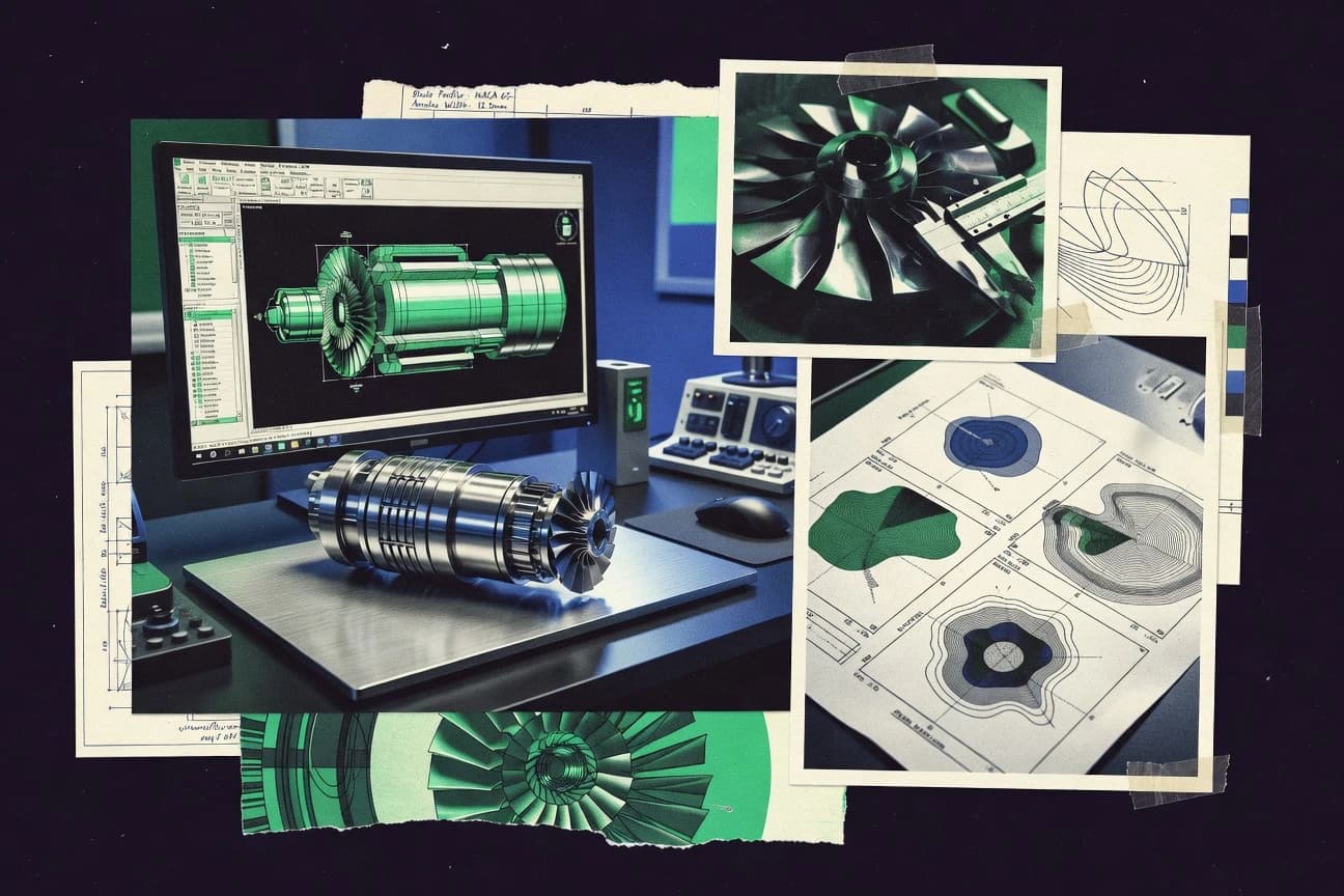
Manufacturing EngineeringTop 10 Best Axial Compressor Design Software of 2026
Axial Compressor Design Software rankings for CFD workflows using CART3D, SU2, and OpenFOAM, comparing top tools for compressor engineers.

How we ranked these tools
Core product claims cross-referenced against official documentation, changelogs, and independent technical reviews.
Analyzed video reviews and hundreds of written evaluations to capture real-world user experiences with each tool.
AI persona simulations modeled how different user types would experience each tool across common use cases and workflows.
Final rankings reviewed and approved by our editorial team with authority to override AI-generated scores based on domain expertise.
Score: Features 40% · Ease 30% · Value 30%
Gitnux may earn a commission through links on this page — this does not influence rankings. Editorial policy
Editor’s top 3 picks
Three quick recommendations before you dive into the full comparison below — each one leads on a different dimension.
CART3D
High-performance unstructured CFD with compressible flow solvers for blade passage analysis
Built for teams validating axial compressor aerodynamics with CFD and detailed meshing control.
SU2
Editor pickAdjoint-driven optimization with sensitivity output for aerodynamic objective functions
Built for turbomachinery teams running research-grade CFD and gradient optimization workflows.
OpenFOAM
Editor pickUser-extensible solver framework for compressible, rotating machinery CFD
Built for cFD-focused teams modeling blade-row losses with solver control.
Related reading
Comparison Table
This comparison table ranks axial compressor CFD design and analysis tools such as CART3D, SU2, OpenFOAM, STAR-CCM+, and ANSYS CFX by integration depth, data model, and automation and API surface. It highlights how each CFD workflow handles meshing and solver configuration through its schema, provisioning, and extensibility features, plus admin and governance controls like RBAC and audit log coverage. The goal is to map which toolchain fits specific orchestration needs across throughput, configuration management, and repeatable simulation runs.
CART3D
CFD solverUses Reynolds-averaged Navier-Stokes and structured or unstructured grids to model turbomachinery flowfields including axial compressor components.
High-performance unstructured CFD with compressible flow solvers for blade passage analysis
CART3D stands out for coupling CFD with geometry and grid workflow suited to aerodynamic analysis around compressors. The software provides structured and unstructured meshing capabilities and supports steady and unsteady flow solutions needed to assess compressor blade and passage performance.
It can model complex turbomachinery-like configurations by combining component geometry with flow solver settings that target compressible aerodynamics. Post-processing supports extracting pressure, forces, and surface flow fields to evaluate design iterations.
- +Strong compressible CFD workflow for compressor-like blade and passage aerodynamics
- +Flexible meshing supports complex internal geometries and unstructured domains
- +Rich outputs for pressure, forces, and surface flow diagnostics during iteration
- –Axial compressor-specific workflows require careful setup of turbulence and boundary conditions
- –Geometry preparation and mesh quality tuning can add substantial engineering time
- –Steady and unsteady runs increase compute cost for detailed design sweeps
CFD engineers in turbomachinery groups
Simulate compressor blade passages under compressible flow
Quicker flowfield validation
Aerodynamic design teams
Assess incidence and loading across compressor stages
Improved stage efficiency
Show 2 more scenarios
Research teams using NASA workflows
Evaluate unsteady effects on compressor components
More reliable aero predictions
Couples geometry, grid generation, and compressible solver settings to study transient blade-row behavior.
Manufacturing-linked design verification staff
Support geometry-to-grid-to-solver design verification
Reduced rework in revisions
Uses mesh generation and post-processing outputs to verify passage quality before building test plans.
Best for: Teams validating axial compressor aerodynamics with CFD and detailed meshing control
More related reading
SU2
CFD optimizationProvides coupled CFD and adjoint-based aerodynamic shape optimization workflows that can model axial compressor blade and stage performance.
Adjoint-driven optimization with sensitivity output for aerodynamic objective functions
SU2 is a research-grade CFD and design platform that supports aerodynamic shape optimization around compressors and turbomachinery workflows. It combines a multi-physics solver stack with gradient-based optimization for high-fidelity analysis of blade and blade-row geometries.
The tool is distinct for pairing consistent adjoint-based sensitivities with configurable turbulence modeling and boundary-condition control. Core capabilities center on aerodynamic performance evaluation, flow-field robustness, and design iterations driven by optimization targets.
- +Adjoint-based sensitivity enables efficient gradient-driven turbomachinery optimization
- +Configurable turbulence modeling supports realistic compressor flow prediction
- +Workflow fits tightly with mesh-based blade and blade-row CFD iterations
- +Strong solver coverage supports multi-physics compressor design extensions
- –Setup complexity is high due to detailed solver and configuration requirements
- –Usability for full axial compressor design automation requires scripting and expertise
- –Debugging convergence issues can be time-consuming for new users
- –Prebuilt axial compressor design templates are limited compared with domain-specific tools
CFD engineers at turbomachinery firms
Design compressor blade rows with adjoints
Faster optimized compressor geometries
University research groups
Study turbulence and boundary effects
Validated sensitivity analysis results
Show 2 more scenarios
Optimization specialists
Perform gradient-based flow-field optimization
Improved stage efficiency targets
Uses gradient-based optimization loops to align objective functions with aerodynamic compressor performance constraints.
Numerical method developers
Prototype multi-physics turbomachinery workflows
Reusable turbomachinery solver pipeline
Couples solver components for multi-physics analysis of blade and row configurations.
Best for: Turbomachinery teams running research-grade CFD and gradient optimization workflows
OpenFOAM
open-source CFDDelivers modular CFD toolchains for building custom axial compressor simulations of internal flow, turbulence, and heat transfer.
User-extensible solver framework for compressible, rotating machinery CFD
OpenFOAM stands out for delivering open, solver-driven CFD and turbulence modeling that supports detailed axial compressor flow physics. It supports compressible, rotating-machine simulations through community and bundled toolchains, including structured and unstructured meshing workflows.
Axial compressor design benefits from coupling geometry, mesh, and physics to resolve shocks, losses, and secondary flows across blade rows. Results rely on user-managed meshing, boundary conditions, and solver setup rather than a compressor-specific interactive design wizard.
- +High-fidelity compressible flow and turbulence modeling for blade-row aerodynamics
- +Rotation-capable simulations using established rotating-frame and interface approaches
- +Full control over numerics, meshing, and boundary conditions for loss mechanisms
- –No dedicated axial compressor design workflow or parametric blade generator
- –Significant setup effort for meshing quality, turbulence settings, and convergence
- –Postprocessing and validation require substantial scripting and CFD expertise
CFD engineers at compressor OEMs
Model compressible blade-row flow with shocks
Improved stage efficiency estimates
Turbomachinery design analysts
Assess secondary flows with rotating frames
Lower endwall loss predictions
Show 2 more scenarios
Research teams validating turbulence models
Compare turbulence closures against data
More reliable turbulence calibration
They couple meshing choices with solver settings to match measured pressure and velocity profiles.
Advanced users building custom workflows
Automate parametric studies across geometries
Faster design-space exploration
They script geometry, meshing, and solver runs to sweep incidence and stagger settings.
Best for: CFD-focused teams modeling blade-row losses with solver control
More related reading
STAR-CCM+
commercial CFDRuns commercial CFD for turbomachinery internal aerodynamics and supports meshing, solver control, and rotating machinery features needed for axial compressor design studies.
Conductor-based scripted mesh workflow that standardizes meshing across compressor design variants
Siemens Simcenter STAR-CCM+ Mesh Conductor focuses on automating mesh creation workflows for CFD runs, which matters for axial compressor design where many geometry variants and operating points require consistent discretization. It supports scripted, parameter-driven mesh generation with conductor-based execution so the same meshing logic can be applied across blade, hub, and casing models.
For axial compressors, its strengths show up in repeatable surface remeshing, boundary-layer setup, and model handoff into solver-ready CFD datasets. Complex meshing edge cases can still require expert tuning of meshing controls and geometry cleanup before automation produces robust results.
- +Repeatable, automated meshing across compressor geometry and operating point sweeps
- +Scriptable meshing steps support consistent boundary-layer and topology handling
- +Conductor workflow streamlines dataset production for iterative CFD design studies
- –Geometry cleanup and meshing-control tuning remain necessary for tough compressor passages
- –Automation setup effort can be high before it stabilizes for production use
- –Mesh failure modes require CFD-specific debugging to restore robustness
Best for: Axial compressor teams needing repeatable CFD meshing automation for design iterations
ANSYS CFX
turbomachinery CFDModels axial compressor rotating and stationary domains with high-fidelity flow physics and supports design iterations through automation interfaces.
TurboGrid automated blade-row structured meshing with H-H and O-H topology control
ANSYS TurboGrid focuses on structured and semi-structured mesh generation for turbomachinery components with an emphasis on repeatable grid creation. It supports H-H and O-H topology options and can generate blade-to-blade grids tailored to axial compressor passage geometry.
The workflow is designed to feed CFD solvers with consistent near-wall resolution and boundary-layer friendly clustering. It is strongest when the compressor design process needs mesh fidelity across many design iterations.
- +Automates structured turbomachinery mesh creation for axial compressor passages
- +Supports H-H and O-H topologies for controlled flow-path resolution
- +Produces consistent grids that reduce CFD setup rework across iterations
- +Boundary-layer friendly control supports near-wall fidelity for blade surfaces
- –Geometry preparation and cleanup are critical for robust meshing
- –Advanced controls require turbomachinery meshing expertise
- –Mesh quality tuning can be time-consuming for unusual compressor layouts
- –Best results depend on accurate periodic and interface definitions
Best for: Teams iterating axial compressor CFD workflows needing high-fidelity structured grids
NUMECA FINE/Turbo
turbo CFDProvides turbomachinery-specific CFD workflows with automated grid generation and performance prediction tailored for axial compressor stages.
Turbomachinery-oriented FINE/Turbo solver workflow with structured-grid handling for axial stages
NUMECA FINE/Turbo focuses on aerodynamic design and analysis for turbomachinery with an emphasis on axial compressors and related components. The workflow combines structured-grid capabilities with CFD solvers designed for turbomachines, plus analysis tools for performance and flowfield evaluation. The solution supports iterative design loops using boundary-condition control, stage modeling, and detailed postprocessing for losses, diffusion, and flow behavior.
- +Strong axial compressor CFD setup with turbomachinery-focused solver workflows
- +Detailed postprocessing for losses, blade loading, and flow structure interpretation
- +Structured-grid orientation and physics controls support repeatable design iterations
- –Best results require CFD expertise and careful meshing for each operating case
- –Workflow can feel heavy for early concept studies and rapid trade-off sweeps
- –Learning curve is steep for defining correct turbomachinery boundary and interfaces
Best for: Teams performing iterative axial compressor CFD design with expert support
More related reading
Siemens Simcenter STAR-CCM+ Mesh Conductor
meshing automationAccelerates repeated CFD meshing and re-meshing for internal flow configurations such as axial compressor components.
Conductor-based scripted mesh workflow that standardizes meshing across compressor design variants
Siemens Simcenter STAR-CCM+ Mesh Conductor focuses on automating mesh creation workflows for CFD runs, which matters for axial compressor design where many geometry variants and operating points require consistent discretization. It supports scripted, parameter-driven mesh generation with conductor-based execution so the same meshing logic can be applied across blade, hub, and casing models.
For axial compressors, its strengths show up in repeatable surface remeshing, boundary-layer setup, and model handoff into solver-ready CFD datasets. Complex meshing edge cases can still require expert tuning of meshing controls and geometry cleanup before automation produces robust results.
- +Repeatable, automated meshing across compressor geometry and operating point sweeps
- +Scriptable meshing steps support consistent boundary-layer and topology handling
- +Conductor workflow streamlines dataset production for iterative CFD design studies
- –Geometry cleanup and meshing-control tuning remain necessary for tough compressor passages
- –Automation setup effort can be high before it stabilizes for production use
- –Mesh failure modes require CFD-specific debugging to restore robustness
Best for: Axial compressor teams needing repeatable CFD meshing automation for design iterations
ANSYS TurboGrid
grid generationGenerates structured turbomachinery grids for blade rows and helps set up axial compressor CFD cases with consistent boundary-layer resolution.
TurboGrid automated blade-row structured meshing with H-H and O-H topology control
ANSYS TurboGrid focuses on structured and semi-structured mesh generation for turbomachinery components with an emphasis on repeatable grid creation. It supports H-H and O-H topology options and can generate blade-to-blade grids tailored to axial compressor passage geometry.
The workflow is designed to feed CFD solvers with consistent near-wall resolution and boundary-layer friendly clustering. It is strongest when the compressor design process needs mesh fidelity across many design iterations.
- +Automates structured turbomachinery mesh creation for axial compressor passages
- +Supports H-H and O-H topologies for controlled flow-path resolution
- +Produces consistent grids that reduce CFD setup rework across iterations
- +Boundary-layer friendly control supports near-wall fidelity for blade surfaces
- –Geometry preparation and cleanup are critical for robust meshing
- –Advanced controls require turbomachinery meshing expertise
- –Mesh quality tuning can be time-consuming for unusual compressor layouts
- –Best results depend on accurate periodic and interface definitions
Best for: Teams iterating axial compressor CFD workflows needing high-fidelity structured grids
More related reading
Pointwise
meshingCreates high-quality block-structured and overset meshes for axial compressor blade and passage geometries used in CFD workflows.
Near-wall boundary layer mesh controls tuned for complex blade passages
Pointwise stands out for generating high-quality structured and unstructured CFD meshes with strong control over axial compressor geometry detail. The workflow supports boundary-layer and turbomachinery-ready meshing around rotating-hardware surfaces. It pairs geometry-aware meshing with solver-agnostic export paths, which fits common axial compressor design and verification loops.
- +High-control mesh generation for compressor blade and hub-shroud passages
- +Strong structured and unstructured meshing options for mixed-grid needs
- +Automated quality sizing supports repeatable parametric compressor iterations
- –Steep setup learning curve for boundary-layer and passage mesh control
- –Iteration speed depends heavily on user scripting and geometry cleanup
- –Advanced meshing workflows can be cumbersome without experienced templates
Best for: Turbomachinery teams needing high-fidelity compressor meshes with repeatable control
Thermoflex
cycle simulationModels thermodynamic cycles and component performance maps that can represent axial compressor behavior in system-level manufacturing and design work.
Integrated engine-cycle coupling that propagates compressor changes into overall performance
Thermoflex stands out for axial compressor and engine-cycle work that couples thermodynamic performance with component matching workflows. The software supports compressor and turbine modeling, mass and energy balances, and parametric runs for off-design and design-point comparisons. Users can iterate on stage-level assumptions and propagate cycle changes into performance maps and key thermodynamic outputs.
- +Axial compressor modeling with cycle-coupled performance outputs
- +Parametric studies for design-point and off-design comparisons
- +Strong support for thermodynamic balances across components
- –Limited stage-by-stage aerodynamic design depth versus dedicated tools
- –Setup can feel configuration heavy for complex configurations
- –Visualization and map editing workflows can be less streamlined
Best for: Engine-cycle and compressor matching teams needing parametric thermodynamic iteration
Conclusion
After evaluating 10 manufacturing engineering, CART3D stands out as our overall top pick — it scored highest across our combined criteria of features, ease of use, and value, which is why it sits at #1 in the rankings above.
Use the comparison table and detailed reviews above to validate the fit against your own requirements before committing to a tool.
How to Choose the Right Axial Compressor Design Software
This buyer's guide covers axial compressor design software workflows across CART3D, SU2, OpenFOAM, STAR-CCM+, ANSYS CFX, NUMECA FINE/Turbo, Siemens Simcenter STAR-CCM+ Mesh Conductor, ANSYS TurboGrid, Pointwise, and Thermoflex.
The focus is integration depth, the underlying data model implied by each workflow, automation and API surface expectations, and admin and governance controls for repeatable compressor design iterations.
CFD workflows are mapped to CART3D, SU2, and OpenFOAM simulation patterns, and meshing automation is mapped to STAR-CCM+ Mesh Conductor, ANSYS TurboGrid, ANSYS CFX TurboGrid, and Pointwise.
Thermodynamic cycle and component matching workflows are mapped to Thermoflex so compressor changes can propagate into performance maps and system-level outputs.
Axial compressor design tooling that connects geometry, CFD physics, and design iteration for blade rows
Axial compressor design software turns compressor geometry, mesh, and operating conditions into analyzable results for blade passage aerodynamics, stage losses, and performance outputs.
Some tools concentrate on compressible CFD for compressor-like blade and passage analysis, like CART3D and OpenFOAM, while SU2 adds adjoint-driven aerodynamic shape optimization for compressor and blade-row geometry changes.
Other tools concentrate on mesh automation and repeatable dataset generation, like STAR-CCM+ Mesh Conductor and ANSYS TurboGrid, so many compressor variants share consistent near-wall resolution and boundary-layer setup.
Thermodynamic cycle and matching tools like Thermoflex connect compressor behavior to system-level mass and energy balances for design-point and off-design comparisons.
Evaluation criteria that matter for axial compressor design integration, iteration, and governance
Axial compressor design work breaks when geometry handling, meshing consistency, and solver setup do not share a common data model across design iterations.
Tools should be evaluated on integration depth into a CFD pipeline, automation and API surface for repeatable runs, and admin and governance controls that protect configuration, outputs, and run provenance.
For teams running CART3D, SU2, and OpenFOAM workflows, the meshing handoff into solver-ready datasets and the scripting surface for batch throughput are the difference between manual reruns and controlled automation.
Adjoint-driven optimization with sensitivity outputs
SU2 provides adjoint-driven sensitivity so optimization can target aerodynamic objective functions using gradient information for axial compressor blade and stage performance tasks. This matters when geometry changes are frequent and optimization iterations must be guided by sensitivities rather than manual trial-and-error.
Unstructured compressible CFD for blade passage aerodynamics
CART3D supports compressible flow solvers with structured or unstructured grids for axial compressor components, and it outputs pressure, forces, and surface flow fields for iteration diagnostics. This fits teams validating blade and passage aerodynamics where meshing flexibility matters more than strict topology control.
Extensible rotating-machine CFD with user-managed physics
OpenFOAM delivers modular solver toolchains that support compressible rotating-machine simulation approaches and blade-row loss modeling, with rotation capability handled through established rotating-frame and interface approaches. This matters for governance-heavy pipelines because solver configuration and numerics are controlled by the user through the toolchain.
Conductor-based scripted meshing with repeatable dataset production
STAR-CCM+ Mesh Conductor standardizes scripted mesh steps across blade, hub, and casing models so many compressor variants share consistent boundary-layer and topology handling. This matters for throughput because it reduces time lost to rerunning mesh setup and keeps CFD datasets consistent across sweeps.
Structured turbomachinery grid generation with H-H and O-H topology
ANSYS TurboGrid and ANSYS CFX TurboGrid focus on structured and semi-structured turbomachinery grids with H-H and O-H topology options for axial compressor passages. This matters when near-wall resolution and flow-path resolution must remain consistent across design iterations.
Near-wall boundary-layer mesh control for complex blade passages
Pointwise emphasizes high-control mesh generation for compressor blade and hub-shroud passages and includes near-wall boundary layer mesh controls tuned for complex blade passages. This matters when geometry detail forces custom boundary-layer tuning that must be repeatable in automated workflows.
Cycle-coupled compressor matching and performance map propagation
Thermoflex models thermodynamic cycles and couples compressor and turbine behavior with mass and energy balances, then propagates compressor changes into overall performance maps. This matters when aerodynamic CFD is one input into system-level matching and parametric off-design and design-point comparisons.
A decision path for selecting axial compressor design software by workflow control depth
Start by selecting the computational role of the tool in the compressor workflow, then verify that the tool can connect to meshing, solver execution, and postprocessing without manual rework.
A CART3D and SU2 and OpenFOAM pipeline generally needs a predictable handoff from mesh generation to compressible CFD configuration, and that requirement shapes which meshing and automation tools fit best.
Automation and governance expectations should be checked by verifying that run inputs, solver settings, and mesh generation steps can be parameterized and executed consistently across iterations.
Pick the CFD role: blade-passage validation, rotating-machine loss physics, or gradient optimization
If the goal is compressor-like blade passage aerodynamics with flexible structured or unstructured grids, CART3D fits because it directly supports high-performance unstructured compressible CFD with pressure, forces, and surface flow diagnostics. If the goal is aerodynamic shape optimization with gradient-driven iterations, SU2 fits because it provides adjoint-driven sensitivities for objective functions. If the goal is user-extensible compressible rotating-machine CFD with detailed loss mechanism control, OpenFOAM fits because it supports solver toolchains for rotating machinery approaches where numerics and turbulence choices are user-managed.
Choose the meshing automation layer that matches the toolchain handoff model
For high iteration throughput where the same meshing logic must be applied across compressor variants, STAR-CCM+ Mesh Conductor fits because it uses conductor-based scripted mesh workflows for repeatable surface remeshing and boundary-layer setup. For teams that need structured turbomachinery topology control across blade rows, ANSYS TurboGrid fits because it supports H-H and O-H options and generates blade-to-blade structured grids. When mixed grid strategies or boundary-layer tuning control dominates, Pointwise fits because it provides near-wall boundary layer mesh controls for complex blade passages and strong structured and unstructured meshing options.
Plan for automation and run configuration reproducibility
If the design loop requires scheduled re-meshing and consistent dataset generation, STAR-CCM+ Mesh Conductor is a strong automation backbone because it standardizes scripted mesh steps across blade, hub, and casing models. If the design loop needs structured near-wall fidelity with automated grid creation across many iterations, ANSYS CFX TurboGrid fits because it emphasizes repeatable turbomachinery grid creation with boundary-layer friendly clustering. If the workflow uses OpenFOAM or other solver toolchains, the automation requirement shifts to scripting around geometry, boundary conditions, and numerics because OpenFOAM depends on user-managed meshing, boundary conditions, and solver setup.
Select governance controls based on who owns solver settings and how errors are caught
For teams that need standardized configuration across operators, tools built around scripted and parameter-driven meshing workflows like STAR-CCM+ Mesh Conductor reduce variability because the same steps apply to many compressor variants. For teams that require solver and numerics control with explicit configuration artifacts, OpenFOAM fits because solver configuration and turbulence modeling choices are handled through toolchain-driven setup. For teams using SU2 optimization, the governance focus shifts to tracking optimization targets and sensitivities because adjoint-driven sensitivity outputs must map cleanly back to objective functions and design variables.
Connect aerodynamic outputs to stage and system-level decision making
For stage-level aerodynamic interpretation with loss and diffusion analysis, NUMECA FINE/Turbo fits because it provides turbomachinery-focused solver workflows with detailed postprocessing for losses, blade loading, and flow structure interpretation. For system-level matching where compressor changes must propagate into performance maps and mass and energy balances, Thermoflex fits because it couples compressor and turbine behavior into cycle-coupled outputs for design-point and off-design comparisons. This step prevents aerodynamic changes from getting stranded in CFD-only artifacts and keeps cycle-level assumptions aligned with compressor updates.
Which teams should select each axial compressor design workflow approach
Axial compressor design tooling splits into three common workflow needs: compressor-like CFD validation, rotating-machine loss prediction, and design optimization or system-level matching.
Selection should follow the stated best-for targets because the tools differ in how much the workflow is tailored to axial compressors versus how much it is solver-driven and user-configured.
Integration depth and automation expectations also differ depending on whether the tool is the CFD engine, the meshing automation layer, or the thermodynamic cycle layer.
CFD teams validating axial compressor aerodynamics with detailed mesh control
CART3D fits this audience because it provides compressible CFD with structured or unstructured grids and outputs pressure, forces, and surface flow fields for iteration. Pointwise also fits when boundary-layer and passage meshing control must be tuned for complex compressor blade passages.
Research and optimization teams running gradient-driven turbomachinery shape changes
SU2 fits because it pairs aerodynamic performance evaluation with adjoint-driven sensitivity output and gradient-based optimization for blade and blade-row geometries. OpenFOAM can fit adjacent research workflows when user-managed solver and rotating-machine physics control is required.
Solver-centric teams modeling blade-row losses with user-controlled physics
OpenFOAM fits because it provides a user-extensible solver framework for compressible, rotating machinery CFD where meshing, boundary conditions, and convergence control are user-managed. NUMECA FINE/Turbo fits teams that still want turbomachinery focus but prefer guided structured-grid handling and loss-focused postprocessing.
Axial compressor teams that need repeatable CFD meshing automation for many variants
STAR-CCM+ Mesh Conductor fits because conductor-based scripted meshing supports repeatable surface remeshing and boundary-layer setup across blade, hub, and casing models. ANSYS TurboGrid fits because it automates blade-row structured meshing using H-H and O-H topology options for consistent near-wall resolution across iterations.
Engine-cycle and compressor matching teams that propagate compressor changes into system performance
Thermoflex fits because it couples compressor behavior into thermodynamic cycles, performs mass and energy balances, and supports parametric design-point and off-design comparisons. NUMECA FINE/Turbo can still fit this audience when aerodynamic stage interpretation must feed matching assumptions.
Common failure points when selecting tools for axial compressor design workflows
Most workflow failures come from mismatched responsibilities across geometry, mesh, solver configuration, and optimization targets.
Axial compressor tooling often looks interchangeable until meshing variability and boundary-condition setup differences accumulate across design iterations.
The following pitfalls map to concrete constraints observed in tools like CART3D, SU2, OpenFOAM, STAR-CCM+ Mesh Conductor, and ANSYS TurboGrid.
Treating axial compressor CFD as a plug-in without boundary-condition and turbulence configuration discipline
CART3D and SU2 can both require careful setup of turbulence models and boundary conditions because compressor blade and passage physics are sensitive to those inputs. OpenFOAM has the same sensitivity but pushes configuration ownership to the user through numerics, turbulence settings, meshing, and boundary conditions.
Building an iteration pipeline on meshing automation that still needs manual geometry cleanup every time
STAR-CCM+ Mesh Conductor standardizes scripted meshing steps but can still require geometry cleanup and meshing-control tuning for tough compressor passages. ANSYS TurboGrid and ANSYS CFX TurboGrid similarly depend on geometry preparation and accurate periodic and interface definitions to avoid mesh failure modes.
Choosing a structured meshing tool without verifying periodic and interface definitions for compressor passages
ANSYS TurboGrid and ANSYS CFX TurboGrid can fail to deliver consistent structured grids when periodic and interface definitions are inaccurate because best results depend on correct definitions. Pointwise and CART3D can reduce strict topology sensitivity by supporting mixed structured and unstructured meshing strategies, but they still require consistent boundary-layer mesh logic.
Mixing optimization and validation outputs without a clear mapping from objective functions to sensitivity outputs
SU2 optimization requires reliable adjoint sensitivities tied to aerodynamic objective functions, so objective definitions and design variables must stay consistent across runs. Without that mapping, optimization loops can generate outputs that cannot be reconciled with CART3D or OpenFOAM validation cases.
Using only thermodynamic cycle matching for decisions that need blade-level loss physics
Thermoflex excels at cycle-coupled performance and stage-level assumptions but has limited stage-by-stage aerodynamic design depth versus dedicated CFD tools like OpenFOAM or NUMECA FINE/Turbo. For loss mechanisms and secondary flow behavior, CFD outputs from CART3D, SU2, or OpenFOAM remain necessary.
How We Selected and Ranked These Tools
We evaluated each tool on features, ease of use, and value using the provided review records for CART3D, SU2, OpenFOAM, STAR-CCM+, ANSYS CFX, NUMECA FINE/Turbo, Siemens Simcenter STAR-CCM+ Mesh Conductor, ANSYS TurboGrid, Pointwise, and Thermoflex. Features carried the most weight because axial compressor workflows depend on compressible CFD capability, meshing repeatability, and optimization or cycle coupling.
Ease of use and value each influenced the final ordering when tools required heavy setup to reach stable design iteration behavior. CART3D separated itself from lower-ranked tools by delivering high-performance unstructured compressible CFD with strong blade-passage diagnostics, and that capability directly raised both its features score and its ease-of-use fit for compressor-like validation workflows.
Frequently Asked Questions About Axial Compressor Design Software
Which tools best support CFD workflows around axial compressor blades using CART3D, SU2, and OpenFOAM?
How do STAR-CCM+ Mesh Conductor and Pointwise differ in handling repeatable meshing across compressor design variants?
Which option supports structured or semi-structured axial compressor passage grids with topology control?
Which tools provide optimization-oriented outputs for compressor aerodynamic objectives rather than just flow solutions?
How should teams choose between OpenFOAM extensibility and turbomachinery-focused workflows in FINE/Turbo or NUMECA FINE/Turbo?
What integration or automation approach works best for running many operating points and geometry iterations?
How do these tools handle rotating-machine requirements such as blade-row interfaces and rotating physics?
What data migration or handoff pattern is typical when moving from a mesher into a CFD solver workflow?
Which tool supports admin control, RBAC, and auditability needs for multi-user compressor design teams?
What extensibility options exist when the required turbulence model, boundary condition, or solver step is not covered by a built-in workflow?
Tools reviewed
Primary sources checked during evaluation.
Referenced in the comparison table and product reviews above.
Keep exploring
Comparing two specific tools?
Software Alternatives
See head-to-head software comparisons with feature breakdowns, pricing, and our recommendation for each use case.
Explore software alternatives→In this category
Manufacturing Engineering alternatives
See side-by-side comparisons of manufacturing engineering tools and pick the right one for your stack.
Compare manufacturing engineering tools→FOR SOFTWARE VENDORS
Not on this list? Let’s fix that.
Our best-of pages are how many teams discover and compare tools in this space. If you think your product belongs in this lineup, we’d like to hear from you—we’ll walk you through fit and what an editorial entry looks like.
Apply for a ListingWHAT THIS INCLUDES
Where buyers compare
Readers come to these pages to shortlist software—your product shows up in that moment, not in a random sidebar.
Editorial write-up
We describe your product in our own words and check the facts before anything goes live.
On-page brand presence
You appear in the roundup the same way as other tools we cover: name, positioning, and a clear next step for readers who want to learn more.
Kept up to date
We refresh lists on a regular rhythm so the category page stays useful as products and pricing change.